...
Table of content
| Table of Contents | ||
|---|---|---|
|
Описание
...
Description
Infinet devices of the InfiLINK 2x2 и and InfiMAN 2x2 включают два модуля для настройки протокола families have two modules for configuring RIP: модуль rip и модуль arip. Различие между ними заключается в том, что модуль rip не поддерживает совместную работу с протоколом OSPF, поэтому рекомендуется выполнять конфигурацию устройств с использованием модуля arip. В соответствии с рекомендацией в статье будем рассматривать настройку протокола RIP с использованием модуля arip.
Конфигурация RIP выполняется только в режиме CLI. Для настройки протокола RIP используется отдельная командная оболочка, включающая в себя несколько режимов (рис. 1). Переход в каждый из режимов выполняется с использованием одноименных команд. Подробное описание команд представлено в технической документации.
...
Базовый режим RIP предназначен для анализа вывода диагностических команд и перехода в режим конфигурации.
...
and arip. The difference between them is in the interoperability with the OSPF protocol, which the rip module does not have, thus it is recommended to configure devices using the arip module. Due to the recommendation, this article will describe RIP configuration using the arip module.
The RIP configuration is performed only via CLI. A separate command shell with several modes is used to configure the RIP protocol (Figure 1). The transition to each mode is performed using the commands with the same name. A detailed commands description is available in Technical documentation.
| Mode name | Description | |||||||
|---|---|---|---|---|---|---|---|---|
| Basic | Basic RIP mode is used to analyze the diagnostic commands output and switch to configuration mode. Switching to basic mode is performed from the WANFleX command shell using the "arip" command.
|
| RIP |
Режим конфигурации позволяет управлять демоном RIP, запущенным на устройстве и выполнять переход в один из конфигурационных режимов, маршрутизатора, интерфейсов или фильтров маршрутов.
Переход в режим конфигурации RIP выполняется из базового режима с помощью команды "config"| configuration | Configuration mode allows to manage the RIP service running on the device and proceed to the configuration modes, router, interfaces, or route-maps. Switching to RIP configuration mode is performed from basic mode using the "config" command.
|
| RIP |
В режиме конфигурации маршрутизатора выполняются основные настройки протокола RIP. Режим позволяет настроить анонсируемые сети, области, идентификатор маршрутизатора и т.д.
Переход в режим конфигурации маршрутизатора RIP выполняется из режима конфигурации с помощью команды "router"Переход в режим конфигурации интерфейса RIP выполняется из режима конфигурации с помощью команды| router configuration | In router configuration mode, basic RIPF settings are made. The mode allows to configure the announced networks, router ID, etc. Switching to the RIP router configuration mode is performed from the configuration mode using the "router" command.
|
Режим конфигурации интерфейса RIP позволяет выполнить настройки протокола, связанные с конкретным интерфейсом.
Режим конфигурации фильтров маршрутов позволяет выполнить настройку правил, применяемых к анонсируемым или принимаемым маршрутам RIP.
Переход в режим конфигурации фильтров маршрутов RIP выполняется из режима конфигурации с помощью команды создания фильтра| RIP interface configuration | RIP interface configuration mode allows to configure the protocol settings related to a specific interface. Switching to the RIP interface configuration mode is performed from the configuration mode using the "interface IFNAME" command.
|
| Route-maps configuration | Route-maps configuration mode allows to configure the rules that should be applied to announced or received RIP routes. Switching to the RIP route-map configuration mode is performed from the configuration mode using the rule creation command "route-map WORD (deny|permit) <1-65535>".
|
| Center | ||||||
|---|---|---|---|---|---|---|
|
Каждый из режимов командной оболочки RIP содержит помощь с выводом всего перечня поддерживаемых команд. Вызов помощи выполняется с использованием команды "help".
...
| Scheme of switching between RIP command shell modes |
Each RIP shell modes provides help by displaying the full list of supported commands. To display the list use the "help" command.
The routing table can be displayed by the following commands:
| Code Block | ||||
|---|---|---|---|---|
| ||||
Из командной оболочки WANFleX: BS_1#1> netstat -r Из командной оболочки RIP: RIP> show route Из командной оболочки ARDA: ARDA> show route |
Постановка задачи
Рассмотрим поэтапную конфигурацию протокола RIP на устройствах Инфинет на примере следующей схемы (рис. 2):
...
Task
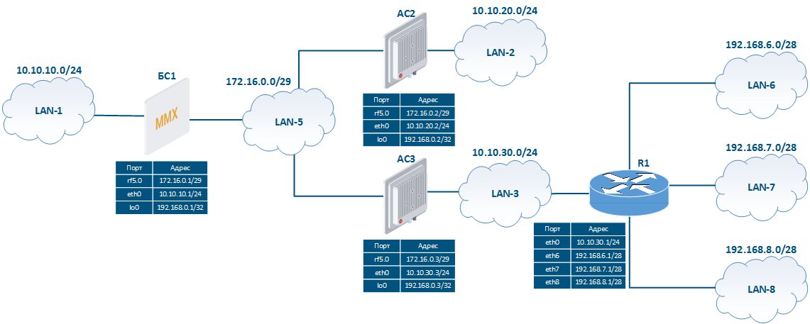
Let's look at the RIP step by step configuration on Infinet devices using the following scheme (Figure 2):
- the network consists of three wireless devices BS1, CPE2 and CPE3 connected by wireless links;
- бsubnet 172.16.0.0/29 ;каждое из беспроводных устройств имеет подключение к проводному сегменту связи: БС1 подключен к сети is assigned to the wireless network;
- each wireless device has a connection to a wired segment: BS1 is connected to the 10.10.10.0/24 network, АС2 CPE2 - к сети to the 10.10.20.0/24 network, АС3 CPE3 - к сети to the 10.10.30.0/24 ;на беспроводном устройстве АС3 настроены три статических маршрута к сетям network;
- three static routes are configured on the CPE3 wireless device to the networks 192.168.6.0/28, 192.168.7.0/28, 192.168.8.0/28. В качестве шлюза используется сторонний маршрутизатор R1;за каждым из беспроводных устройств закреплён адрес, ассоциированный с интерфейсом loopback, из сети The third-party router R1 is used as a gateway;
- to the loopback interface of each wireless device is assigned an address from the 192.168.0.0/24 network.
Задача: на беспроводных устройствах необходимо настроить работу протокола RIP так, чтобы в таблице каждого из маршрутизатором появилась информация о всех сетях, указанных на схеме. Устройство БС1 должно быть использовано в качестве шлюза по умолчанию на устройствах АС2 и АС3.
| Center |
|---|
Рисунок 2 - Пример схемы сети для конфигурации протокола RIP |
Решение
Выполним поэтапную конфигурацию устройств в соответствии с поставленной задачей. Помимо конфигурации RIP будем использовать статическую маршрутизацию (см. Статическая маршрутизация) для организации связи с Task: configure the RIP operation on wireless devices to add information about all the networks in the scheme to the routing table of each router. The BS1 device should be used as the default gateway on the CPE2 and CPE3 devices.
| Center |
|---|
Figure 2 - Network scheme for RIP configuring example |
Solution
Perform the devices step by step configuration in accordance with the task. In addition to the RIP configuration, the static routing will be used (see. Static routing) for connection with LAN-6, LAN-7, LAN-8.
Поскольку пример носит демонстрационный характер, то для настройки протокола RIP на беспроводных устройствах будут использоваться различные подходы.
Предварительная настройка
...
Выполним предварительную настройку устройств, состоящую из следующих этапов:
- Установка идентификаторов устройств.
- Удаление интерфейса svi1.
- Ассоциация IP-адресов с сетевыми интерфейсами, согласно схеме.
- Добавление статических записей в таблицу маршрутизации.
- Отключение коммутации.
- Установка радиоканала.
...
To demonstrate more features in the example, different approaches will be used to configure RIP on wireless devices.
Pre-configuration
| Description | Perform a devices preliminary configuration consisting of the following steps:
| |||||||
|---|---|---|---|---|---|---|---|---|
| BS1 |
| |||||||
| АС2CPE2 |
| |||||||
| АС3CPE3 |
|
...
RIP configuration
| Описание | Description | Configure the RIP protocol in accordance with the scheme. Step 1: start RIP daemon. Step 2: define the interfaces where RIP should be started:
In the CPE2 router configuration, the range of networks used in RIP will be set as a single entry 0.0.0.0/0. Такая запись включает в себя все сети и активирует поддержку RIP на всех интерфейсах маршрутизатора, при подключении одного из интерфейсов устройства к новой сети эта сеть будет сразу анонсирована через RIP. Такой подход имеет преимущество, т.к. не потребуется дополнительной конфигурации RIP, но он таит в себе недостаток, т.к. снижается контроль за анонсами. На маршрутизаторах БС1 и АС3 будем указывать только те сети, которые ассоциированы с интерфейсами, участвующими в работе протокола RIP. Этап 3: выполним редистрибуцию маршрутной информации. БС1 выполняет редистрибуцию непосредственно присоединённых сетей, АС3 - редистрибуцию статических маршрутов. Этап 4: определим пассивные интерфейсы. Интерфейс eth0 маршрутизатора АС3 подключен к стороннему маршрутизатору R1, поэтому необходимо блокировать передачу маршрутной информации между ними. Для этого интерфейс eth0 АС3 необходимо настроить как пассивный. Этап 5: анонсируем маршрут по умолчанию, указав в качестве шлюза БС1. | БС1This entry includes all networks and enables RIP support on all router interfaces; when some device interfaces is connected to a new network, this network will be immediately announced via RIP. This approach doesn't require additional RIP configuration, but decreases control over announcements. On the BS1 and CPE3 routers, we will be set only those networks that are associated with the interfaces participating in the RIP operation. Step 3: make redistribution of directly connected networks on the BS1 router and static routes on the CPE3 router. Step 4: configure passive interfaces. The CPE3 eth0 interface is connected to the outside router R1, therefore it is necessary to block the routing information transmission between them. To ensure this, the CPE3 eth0 interface must be configured as passive. Step 5: announce the default route, specifying BS1 as the gateway. | |||||
|---|---|---|---|---|---|---|---|---|
| BS1 |
| |||||||
| АС2CPE2 |
| |||||||
| АС3CPE3 |
|
Анализ вывода команд
Таблица маршрутизации
...
В таблицах маршрутизации беспроводных устройств видно, что каждое устройство владеет маршрутом к каждой подсети, представленной на схеме. Это свидетельствует о том, что устройства успешно обменялись маршрутной информацией и добавили её в FIB.
Следует обратить внимание на то, что в таблице маршрутизации каждого из устройств присутствует маршрут к адресам, закреплённым за интерфейсами loopback других беспроводных устройств. Эти интерфейсы были включены в RIP различными способами:
- БС1: редистрибуция непосредственно присоединённой сети;
- АС2: устройство анонсирует все сети, к которым имеет подключение;
- АС3: явное указание анонсов сети, закреплённой за интерфейсом loopback.
Также следует обратить внимание на наличие маршрута по умолчанию на устройствах АС2 и АС3. БС1, в соответствии с конфигурацией, анонсирует всем устройствам, поддерживающим работу протокола RIP, маршрут по умолчанию, указывая себя в качестве шлюза. При этом в таблице маршрутизации БС1 маршрут по умолчанию отсутствует.
...
Command output analyzing
Routing table
| Description | The routing tables of wireless devices, contains entries that each device has information about each subnet shown in the scheme. This means that the devices have successfully exchanged routing information and added it to the FIB. Note the devices routing table contains a route to the addresses assigned to the loopback interfaces of other wireless devices. These interfaces have been added to RIP in various ways:
Also pay attention to the default route on CPE2 and CPE3 devices. in accordance with the configuration, BS1 announces the default route to all devices that support RIP, indicating itself as a gateway. At the same time, the default route is absent in the BS1 routing table. The CPE3 router redistributes static routes, therefore, the BC1 and CPE2 routing tables contain paths to the networks 192.168.6.0/24, 192.168.7.0/24 |
|---|
and 192.168.8.0/24. |
| BS1 |
|
|---|
| CPE2 |
|
|---|
| CPE3 |
|
|---|
Дополнительные материалы
Онлайн-курсы
Прочее
...