Successfully pass the free certification exam at IW Academy and become an Infinet Certified Engineer.
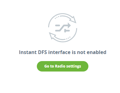
This section allows to monitor the Instant DFS tool operation in real time. To display the data in this section, the frequency selection must be set to "Instant DFS" or "Instant DFS and radar detection" mode. To enable the required mode, go to the "Radio" section.
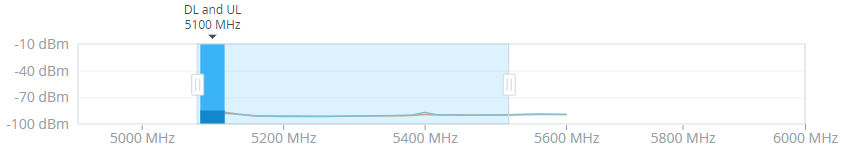
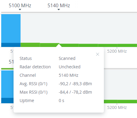
At the top of the section there is information about the status of each band participating in the scan in accordance with the frequency grid. The upper stripe displays the band status discovered by the radar detection tool. The columns show the signal levels detected by the Instant DFS tool. There is the RSSI scale displaying the level of the detected signal in this band at the left side. Band statuses are described in the legend at the bottom of the section.
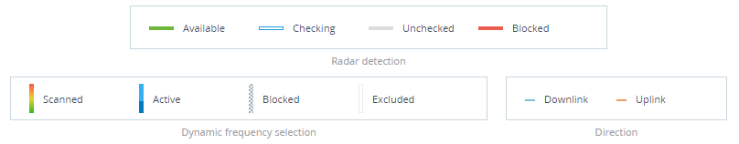
Scanning is performed in two directions:
- Uplink - scans the spectrum state on the Master side.
- Downlink - scans the spectrum state on the Slave side.
Enabling the "Instant DFS" mode on one device automatically starts the scanning process at the remote end of the link.
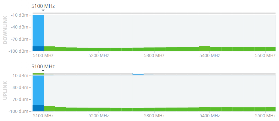
Detailed information about the band status can be obtained by clicking on the corresponding column.
Use sliders on the scale at the bottom of the section to zoom in or zoom out the layout.