Page tree
Skip to end of metadata
Go to start of metadata

You are viewing an old version of this page. View the current version.

Compare with Current View Page History

Version 1 Next »

The radio page is divided in two sections:

  • "Radio settings" - allows you to configure  general  radio parameters and features:
    • General parameters
    • Radio Front End
    • Modulation
    • Radio frame
  • "Frequency Grid and Limitations" - specifies the  default and custom  frequency domains for each  bandwidth (10 MHz, 20 MHz, 40 MHz).

Radio settings

The following radio parameters can be configured under the "Radio settings" section:

Radio parameterDescription
Node Type
  • Set the node type to Master or Slave
  • In the point-to-point link, one unit must be set to Master and the other one to Slave
QoS Strategy
  • You can use this parameter to select the traffic prioritization strategy. The following options are available:
    • normal” provides a balance between packet loss and throughput. It is used by default.               
    •  “aggressive” gives maximum throughput with a minor priority packet loss allowed
    • conservative” assures no priority packet loss, but with small decline in the peak throughput
    • off” disables prioritization
Link ID
  • Use this parameter to avoid connecting a unit to a wrong peer if there are several co-located units using the same center frequency
  • Specify different ID values for different link. Both ends of the same link must have the same ID. The value range is 0…15 in increments of 1
Downlink Frequency
  • Allows you to configure the downlink center frequency in MHz (can be different from the UL frequency for the models which support H-FDD)
  • Downlink Frequency refers to the set frequency for communication in downlink direction - from the Master unit to the Slave unit
Uplink Frequency
  • Allows you to configure the uplink center frequency in MHz (can be different from the DL frequency for the models which support H-FDD)
  • Uplink Frequency refers to the set frequency for communication in uplink direction - from the Slave unit to the Master unit
Channel Width
  • Allows you to configure the channel width (in MHz). The possible values are: 10, 20 or 40 MHz
Transmit Power
  • Allows you to configure the transmit power level (in dBm). The value range is 0…27 dBm in increments of 1 dBm
Maximal  MCS
  • Allows you to configure the maximum MCS that can be used
AMC Strategy
  • Allows you to select the AMC algorithm strategy:
    • “conservative” assumes using higher CINR thresholds in order to minimize the error rate
    • “aggressive” lowers the thresholds in order to use higher modulation levels and thus increase the throughput
    • “normal” represents a balance between the error rate and throughput values
TDD Synchronization
  • Allows you to configure the TDD synchronization source:
    • freerun” unsynchronized frame start
    • gnss” synchronization from built-in GPS/GLONASS receiver
Frame period (ms)
  • Allows you to set the air frame period duration (in ms). The value range is 1, 2, 5 or 10 ms
    • A shorter frame period gives lower latency, but also has higher overheads
    • Using longer frame periods cuts down overheads, but increases the latency
    • Also, air frames higher than 2 ms allow using the link at higher distances

Requested Downlink Quota

(%)
  • Allows you to set the desired downlink/uplink ratio through specifying the downlink subframe period relative to the whole frame. The value range of the parameter is 10…90 in increments of 1
  • Actual downlink/uplink ratio might be different due to internal system limitations. The system chooses the closest available ratio automatically which can be checked in the Status page or by checking the output of the “xg capabilities” command
Max Distance (meters)
  • Allows you to specify the maximum link distance (in meters)
  • The specified value must not be lower than the actual link distance, but it is recommended keep it as close as possible to the actual distance to avoid unnecessary overheads
  • The recommended strategy is to set this parameter well above the actual distance and fine-tune it to actual distance plus 200-300 m after the units have been deployed based on the measured distance value taken from “xg stat” output
Table - Radio settings

CAUTION

 Setting the source of synchronization takes effect only for the Master unit.

CAUTION

 Make sure that the built-in GNSS receiver is set up before enabling the “gnss” option (use “gps” command to check the status - it is recommended to use values of “HDOP” parameter up to 1.5 for reliable global timing synchronization)

CAUTION

 Please note that the following settings must be equal for the co-located units:

  • Channel width
  • Maximal distance
  • Air frame period
  • Downlink/uplink ratio
  • All co-located units must be Master units

Frequency Grid and Limitations

The licensed frequencies range per each bandwidth is displayed in the “Default Frequency Limitation” fields:

  • For 10 MHz bandwidth: value range between 4905...5995 MHz in increments of 10 MHz
  • For 20 MHz bandwidth: value range between 4910...5990 MHz in increments of 20 MHz
  • For 40 MHz bandwidth: value range between 4920...5980 MHz in increments of 20 MHz

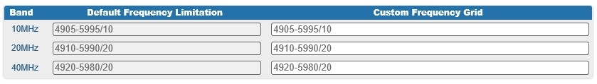
    Figure - Default frequency grids

Changes to these default values can be performed in the “Custom Frequency Grid” fields, whre you can:

  • Limit the licensed frequencies range per each bandwidth
  • Change the center frequency step (for example, 4950-5900/2.5 means that the step between the center frequencies from 4950 GHz and 5900 GHz is 2.5 MHz):

Figure - Custom frequency grids

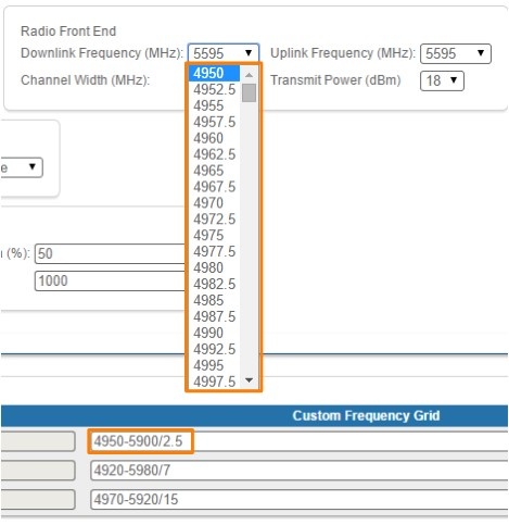
The step must be >= 1 MHz and the frequencies range (determined by the license) cannot be exceeded.

  • No labels