The following configuration can be performed in order to customize the VLAN-based switching operation of the InfiLINK XG unit:
- Create management VLAN
- Allow single VLAN and change of operational port mode
- Configure a native VLAN
- Allow multiple VLANs
- Assign per-VLAN 802.1p priorities (also described in the Configuring QoS section).
Switch default configuration works as transparent Layer2 bridge. Therefore, by default any frames with any VLAN tags (and untagged frames too) will flow freely through wireless link.
Management VLAN configuration
It is possible to add management VLAN configuration and to keep transparent Layer2 bridging operational. It is the simpliest and sufficient configuration for vast number of cases.
- Go to the "Network Access" menu page in the Web interface. Add the management IP address and associate it with VLAN 100 (example):

- Click the “Apply” button to save the changes
NOTE
Now, our InfiLINK XG has two management interfaces:
- 10.10.10.10 for untagged frame
- 10.10.20.1 for VLAN 100
Security considerations imply to remove management interface for untagged frames, leaving only management VLAN access operational.
Meanwhile, such simple, yet efficient configuration do not allow to restrict any other VLAN transport except management VLAN.
In order to allow switching of selected VLANs only, please proceed to next chapters.
Allow single VLAN and change of operational port mode
First: enable VLAN-based Switching.
Once the VLAN-based switching is enabled, the default switching configuration is automatically displayed and it shows the Default VLAN as "native" VLAN for all ports:

NOTE
"Default VLAN" (or VLAN 1) is the only defined VLAN and it cannot be deleted. Multiple VLANs can be afterwards added and configured as desired for each port.
All ports are by default in "trunk" mode, but the native VLAN allows both tagged and untagged traffics to pass. The operational mode of a port is described below.
Now only traffic allowed in VLAN-based Switching matrix is allowed.
Second: you can allow transport of new VLAN by click the «Add VLAN» button.
- Click the “Add VLAN” button
- VLAN 2 is added by default. Modify the value for the VLAN tag according to the actual requirements
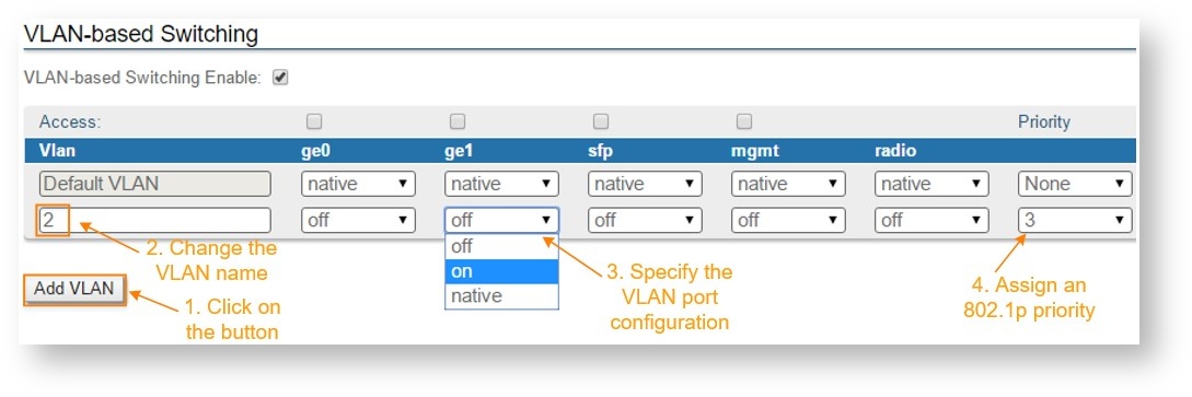
- The VLAN just added is by default disabled (off) on all ports. The following options are available for the port configuration:
Assign an 802.1p priority. The packets received at the wired interfaces can be marked with an 802.1p priority. “0” is the lowest priority and “7” the highest
The following options are available for VLAN configuration:
- "Access mode" - allows untagged traffic from certain VLAN only
- "Trunk mode" - allows tagged traffic only
To configure the access or trunk mode, you need to enable or disable the “Access” checkbox for each port. In the example below, the "ge0" port is in "trunk" mode and "ge1" is in "access" mode.

To send and receive tagged and untagged traffic the "native VLAN" option should be used. "native VLAN" defines the VLAN tag number, which can receive all incoming untagged traffic (for example, by default VLAN1 is configured as a "native VLAN" for all the ports).
In order to allow both tagged and untagged traffic to pass in the "trunk" operational mode, a "native VLAN" can be configured. The details about the "native VLAN" and specific operation are described in the following section Configuring native VLAN.
NOTE
- "Priority" - use this option to set the priority to the certain VLAN in compliance with 802.1p, from 0 to 7 in increments of 1
- "Port state" - allows you to specify if a VLAN should be allowed to pass by the port (on), denied (off) or if the VLAN should be a native one for the specific port (native). Only one "native VLAN" per port.

Configuring native VLAN
Port that is set to the "trunk" operational mode allows only tagged traffic to pass. However, one of the VLANs allowed to pass through that port can be configured as native VLAN and it will be the only VLAN that will allow to pass all the untagged traffics at the reception. Therefore, the native VLAN will pass both tagged and untagged traffic.
NOTE
There can be maximum one "native VLAN" for each port
The "Default VLAN" or VLAN 1 is by default configured as "native VLAN" for all the ports:

You can customize the native VLAN configuration according to the specific requirements. For example, there can be ports that should allow only tagged traffic to pass and ports that allow both tagged and untagged traffic.
For example,
Ports "ge0" and "ge1" should allow only VLANs 10 and 20 to pass. Additionally, port "ge1" should also allow the untagged traffic.
In this case, no "native VLAN" should be configured for the "ge0" port and port "ge1" should have VLAN 10 or 20 configured as "native VLAN". The "Default VLAN" should be set to “off” on both ports, otherwise VLAN 1 will be allowed to pass!

NOTE
NOTE
When a different VLAN besides the "Default VLAN" is set as native, the “native” option becomes unavailable for all other VLANs. In order to change the "native VLAN" in this case you have to first remove the current "native VLAN" by changing the state to “on” or “off”. After this, the “native” option is again available for all other VLANs.
Allow multiple VLANs
This section will describe step by step how to configure separate VLANs for management and for the data traffic as follows:
NOTE
In order to configure the VLAN based management access, it is necessary to associate the IP address of the management interface with the management VLAN 100. If you begin by enabling the VLAN-based switching and remove the "native VLAN", you will lose contact with the unit and ERConsole must be used for recovery.
- Go to the "Network Access" menu page in the Web interface. Add the management IP address and associate it with VLAN 100
- Click the “Apply” button to save the changes
NOTE

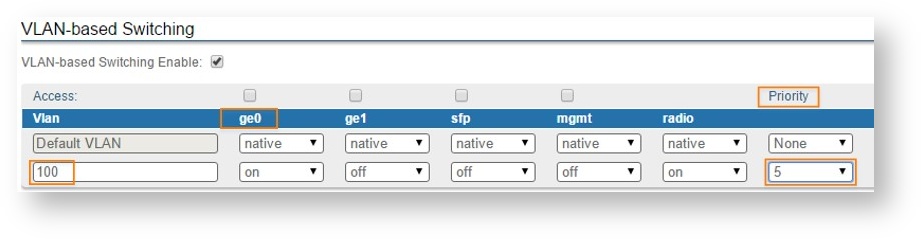
- Add VLAN 100 and allow it to pass through the "ge0", "mgmt" and "radio" ports. This way, the management will be enabled both locally and over the air using VLAN 100
- The "Default VLAN" cannot be removed, so it is necessary to set it "off" on all the ports in order to deny access to untagged traffic (native) or tagged traffic with VLAN 1
- Add VLAN 200 for the data traffic and allow it to pass through the "ge0" and "radio" ports. Since management is not allowed on VLAN 200, it should be set to “off” at the "mgmt" port
- Click the “Apply” button to save the changes.
At this point, the access to the unit is allowed using only VLAN 100 and the newly assigned IP address. Traffic tagged with VLAN 200 will be switched only between the "ge0" and the "radio" ports. Untagged traffic or tagged traffic with other VLANs besides 100 or 200 is not allowed!
Trunk and Trunk VLAN example
Installation which requires VLAN tagged frames to flow in both directions through InfiLINK XG wireless link, does not require any specific configuration. Just due to security reasons it is recommended to set up Management VLAN. All the rest configurartion is not needed in most cases, except the issue to deny certain VLANs. Please, use the configuration steps from chapter Management VLAN configuration.
Access and Trunk VLAN example
Another example is very common for ISP installation. One InfiLINK XG receives VLAN tagged frames from switch trunk port (port configured to carry frames with different VLAN tags), another InfiLINK XG connects with end-customer LAN with requirement to egress untagged frames from certain VLAN only. Please see the diagram below

Brief actions to configure for XG1:
Brief actions to configure for XG2:
- Create management VLAN 100
- Enable VLAN-based switching
- Add VLAN 100, 200
- Set access port settings for VLAN 200
Configuration of XG1
- Go to the "Network Access" menu page in the Web interface. Add the management IP address and associate it with VLAN 100:
- Click the “Apply” button to save the changes

- Add VLAN 100 and allow it to pass through the "ge0", "mgmt" and "radio" ports. This way, the management will be enabled both locally and over the air using VLAN 100
- The "Default VLAN" cannot be removed, so it is necessary to set it "off" on all the ports in order to deny access using untagged traffic (native) or traffic tagged with VLAN 1
- Add VLAN 200 for the data traffic and allow it to pass through the "ge0" and "radio" ports. Since management is not allowed on VLAN 200, it should be set to “off” at the "mgmt" port
- Click the “Apply” button to save the changes.
Configuration of XG2
- Go to the "Network Access" menu page in the Web interface. Add the management IP address and associate it with VLAN 100:

Click the “Apply” button to save the changes
- Go to the "Switch" menu page and enable "VLAN-based Switching":
- Add VLAN 100 and allow it to pass through the "mgmt" and "radio" ports. This way, the management will be enabled over the air using VLAN 100
- The "Default VLAN" cannot be removed, so it is necessary to set it "off" on all the ports in order to deny access using untagged traffic (native) or tagged traffic with VLAN 1
- Add VLAN 200 for the data traffic and allow it to pass through the "ge0" and "radio" ports. Since management is not allowed on VLAN 200, it should be set to “off” at the "mgmt" port
- Mark "Access" checkbox for "ge0" in order to remove all tags for traffic to customer’s LAN

- Click the “Apply” button to save the changes
At this point, the access to the unit is allowed using only VLAN 100 and the newly assigned IP address. Traffic tagged with VLAN 200 will be received by "radio" port and switched untagged to customer’s LAN through "ge0" port.