General information
Link Aggregation is a method of aggregating multiple network connections in parallel in order to increase throughput beyond what a single connection could sustain and to provide redundancy in case one of the links should fail. A Link Aggregation combines a number of physical ports together to make a single high-bandwidth data path, so as to implement the traffic load sharing among the member ports in the group and to enhance the connection reliability.
LACP
Link Aggregation Control Protocol (LACP) is a signaling protocol which provides a method to control the bundling of several physical ports together to form a single logical channel. LACP allows a network device to detect a faulty channel because this protocol sends special LACP packets to a peer. LACP has two standard drafts: old IEEE 802.3ad and new IEEE 802.1AX. LACP service messages are encapsulated directly into Ethernet frames, LACP does not use higher level protocols. The service messages are sent to the multicast MAC address 01-80-c2-00-00-02.
InfiNet Wireless devices have the full support of LACP according to the standard IEEE 802.3ad. Moreover, our devices support special proprietary an extension of LACP. LACP Fast mode increases efficiency and performance compared default mode. The fast mode provides next advantages: faster reaction to changes of links, intellectual estimation quality of the links, more accurate statistical data.
Load balancing
LAG consists of several physical interfaces. Devices need to determine which of the interfaces to send each received packet. All packets from the same data stream must be sent to one physical port to save an order of the stream. For example, TCP protocol can define a wrong order of the packets in the stream as a packet loss; a remote device may not be able to buffer packets for a long time and this will increase jitter and delay - lack of both of these distortions very important for VoIP protocol.
Attention
Load balancing in LAG cannot always be equable, and this will cause some issues.
Radio link aggregation
The Infinet devices allow aggregate several radio links to increase summary throughput. Moreover, you can build Full Duplex link through TDMA.
Redundancy
Infinet devices support full 1 + 1 redundancy schemes. A hot reserve is provided by duplicating transmitting and receiving elements. It is possible to use a single frequency for the redundancy.
R5000
Attention
Configurations from the scenarios below are examples that demonstrate the potential capabilities of Infinet devices. The configuration may change depending on the model and firmware version. Do not recommend copying the solution data to the hardware without checking.
The configuration of LAG (LACP)
Description
The maximum throughput of a single port is limited to the standard 100Base-TX. The throughput of the radio module depending on the MCS and the channel width can be higher. R5000 devices of Lite series can achieve the maximum throughput up to 180 Mbps of the bi-directional aggregated stream. It is not possible to use the maximum throughput of the radio channel in one direction through one 100Base-TX port. However, the combination of ports into one LAG allows achieving the maximum throughput in one direction.
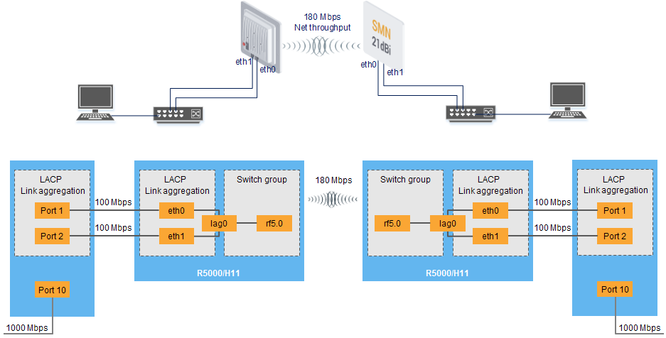
Also, this scenario can be used in point-to-multipoint topologies.
Configuration via GUI
- Create LAG interface

- Add ports
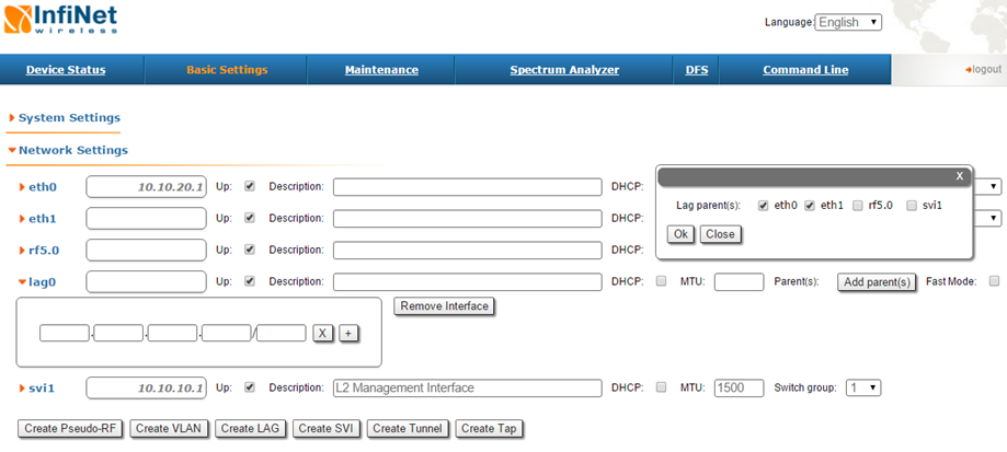
Choose LACP (Standard or Fast mode). "Standard" LACP fully complies with the standard IEEE 802.3ad. “Fast” LACP uses only with Infinet devices and increases efficiency and performance compared default mode.
Attention
The "Fast" mode is a proprietary extension of the LACP protocol. Compatibility of this mode is guaranteed only with devices that support the MINT protocol.
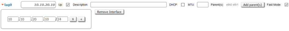
- Configure management IP for LAG interface or SVI (optionally)
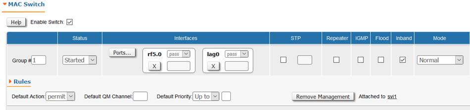
- Configure switch group
Configuration via CLI
lag N [command] [(port|-port) (IFNAME | IFNAME...)]
| Command | Description |
|---|---|
lag N port (IFNAME | IFNAME...)] | Create LAG with name “lagN” and add ports |
lag N status | Check the status of LAG with name “lagN” |
lag N migrate lag N -migrate | Allow/disallow existing sessions migration between the available parent interfaces in case of the difference in the overload. By default, migration is allowed |
lag N balance lag N -balance | Allow/disallow load-depending dispersion of new-coming sessions between the available parent interfaces. By default, balancing is enabled |
lag N mode | Choose LACP (Standard or Fast mode). "Standard" LACP fully complies with the standard IEEE 802.3ad. “Fast” LACP uses only with Infinet devices and increases efficiency and performance compared default mode Attention The "Fast" mode is a proprietary extension of the LACP protocol. Compatibility of this mode is guaranteed only with devices that support the MINT protocol. |
lag N clear | Delete LAG with name "lagN" |
lag N loadm | Show a load statistics in real time on each of the parent interfaces |
Example
The basic configuration of Link Aggregation. The configuration via GUI is described above.
Configuration via CLI:
Create LAG
Creating LAGlag 0 port eth0 eth1 ifc lag0 up
Configure management IP for a LAG interface or SVI (optionally)
Creating Managmentifc lag0 10.10.10.1/24
Configure switch group
Creating Managmentswitch group 1 add 2 rf5.0 lag0 switch group 1 start
Redundancy of a radio link using the same frequency or redundancy of a channel which built on another technology (Failover)
Description
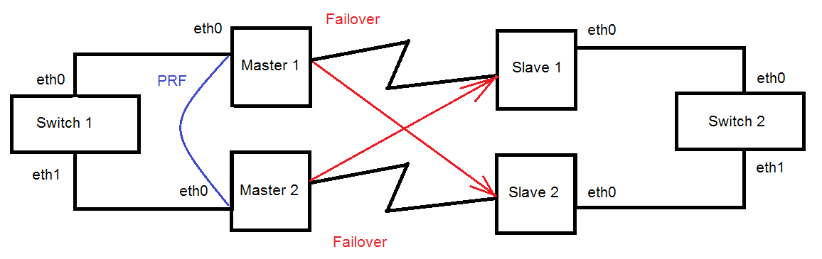
Infinet R5000 devices have a functional redundancy of the channels. A hot standby might be created by using the Failover option. The Failover option does not depend on the method of data transmission on the main channel.The only condition is connectivity at level 2 between Infinet devices through both links.
The principle of operation is extremely simple. The Infinet device, on which the Failover option is configured, checks the availability of a specific MAC address through the primary link. If this MAC address is available, then the operation of the backup channel is blocked. The radio module stops broadcasting on the backup master. The standby slave device only listens to the radio while there is no signal from the master. Thus, the backup link can operate on the same frequency as the main one, but it does not have any influence on it. As soon as the monitored MAC address disappears in the main link, the backup link will be unlocked and traffic will begin to be transmitted over it. The process is completely automatic. However, the transition to a backup link is associated with a short-term idle time. Traffic will return automatically to the primary link as soon as the monitored MAC address appears in the primary link.
If the equipment used in the R5000 series is used as the main link, this gives additional advantages. In this case, both radio links can be configured with the Failover option. For both communication channels, the quality of the established connection will be automatically evaluated. Connection with the worst indicators will automatically become a backup channel. The channel selection parameters can be controlled manually.
You can also install two Infinet devices with a single antenna connection or similar frequency.
1) Manual choice of "MAC"
2) Automatic choice of "MAC"
mint IFNAME [-]failover {MAC|auto}
| Command | Description |
|---|---|
mint IFNAME failover MAC | Configure Failover option to check "MAC" availability |
mint IFNAME failover auto | Configure Failover option to check "MAC" availability. "MAC" will be chosen in automatic mode |
mint IFNAME [-]failover | Disable Failover |
Example
A management is VLAN 100 inside a switch group 100. A transport of user data is inside a switch group 1.
Attention
STP protocol may block correct working Failover option. Failover option causes short-time loops in one broadcast domain.
Configure first radio link
Configure second radio link
Create united MINT domain
1) Manual choice of "MAC"
2) Automatic choice of "MAC"
Configure switch groups
Attention
The number of the switching group for data transmission on Master 2 and Slave 2 devices must differ from the number of such a group on the devices Master1 and Slave 1
Turn on the Failover option
1) Manual choice of "MAC"
2) Automatic choice of "MAC"
Make one of the links as backup link
The backup link must be defined manually when both costs of the radio links are equivalent
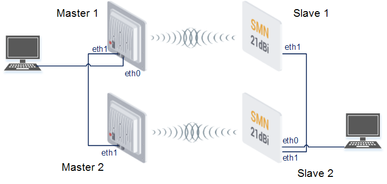
Redundancy without using switches
Description
Infinet devices allow creating redundancy topologies without using switches.
Example
A management is VLAN 100 inside a switch group 100. A transport of user data is inside a switch group 1.
Configure first radio link
Configure second radio link
Turn on POE on port eth1 (optionally)
Create united MINT domain
Configure switch groups
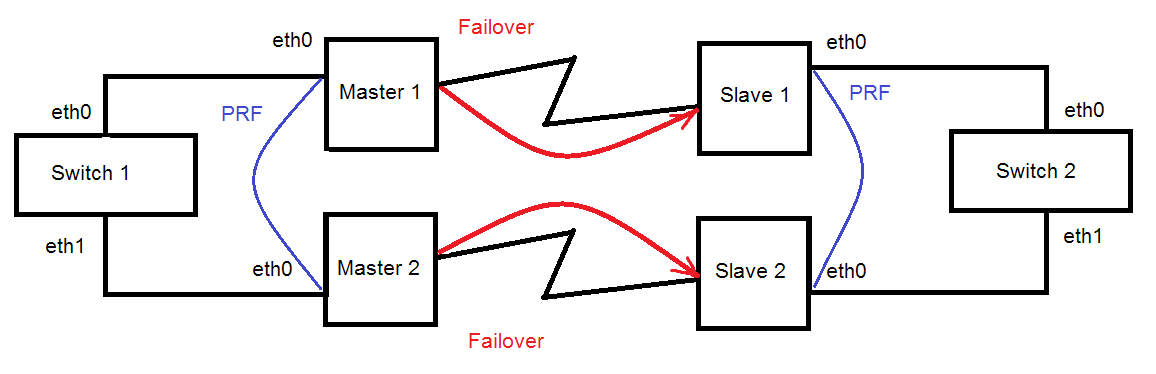
Redundancy of a radio link without aggregation of channels (without using Infimux switches)
Description
It is easy to fully reserve a connection by combining two radio channels into one MINT domain. The traffic path will be automatically selected based on the quality of each radio link in this case.
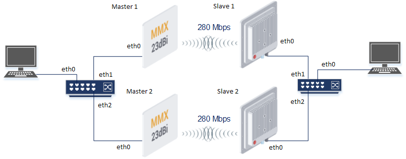
Example
A management is VLAN 100 inside a switch group 100. A transport of user data is inside a switch group 1.
Create first radio link
Create second radio link
Configure switches (Switch configuration is not included in this example)
Create united MINT domain
Configure switch groups
Attention
If you do not exclude the interface eth0 on one of the devices or do not enable STP, then there will be a loop
The STP protocol is used to eliminate the loop In the example below
Redundancy of radio link with aggregation of channels (without using Infimux switches)
Description
It is easy to fully reserve a connection by combining two radio channels into one MINT domain. If you configure the aggregation of channels, you can increase the maximum throughput of the entire radio link.
Example
A management is VLAN 100 inside a switch group 100. A transport of user data is inside switch groups 1 and 2.
Create first radio link
Configure second radio link
Configure switches (Switch configuration is not included in this example)
Create united MINT domain
Configure switch groups
Attention
The number of the switching group for data transmission on Master 2 and Slave 2 devices must differ from the number of such a group on the devices Master1 and Slave 1
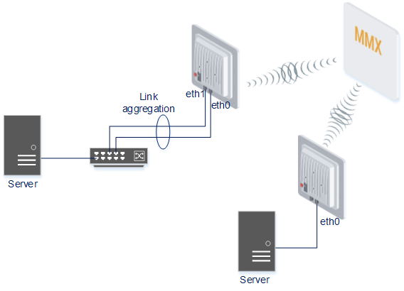
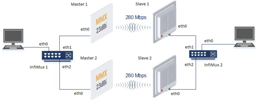
Increasing max radio link throughput (by using switches Infimux)
Description
Link aggregation of radio channels allows increasing the maximum radio throughput. Infimux switches can aggregate radio links into a single MINT domain where a capacity of each link will be estimated in real time.
Example
A management is VLAN 100 inside a switch group 100. A transport of user data is inside a switch group 1.
Configure first radio link
Configure second radio link
Configure InfiMux switches
Create united MINT domain
Configure switch groups
Attention
The number of the switching group for data transmission on Master 2 and Slave 2 devices must differ from the number of such a group on the devices Master1 and Slave 1
Full Duplex radio link
Description
The radio link always works in Half Duplex mode. However, MINT technology allow organizing Full Duplex channels.
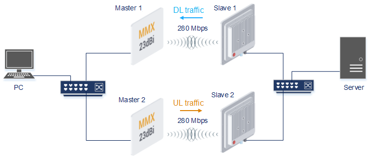
Example
A management is VLAN 100 inside a switch group 100. A transport of user data is inside a switch group 1.
Configure first radio link
Configure second radio link
Configure switches (Switch configuration is not included in this example)
Create united MINT domain
Configure switch groups
Attention
If you do not exclude the interface eth0 on one of the devices or do not enable STP, then there will be a loop
Configure cost of links in united MINT domain
XG
At the moment there is no good solution without minuses. Details in the case SUP-616 - Getting issue details... STATUS .
Attention
Configurations from the scenarios below are examples that demonstrate the potential capabilities of Infinet devices. The configuration may change depending on the model and firmware version. Do not recommend copying the solution data to the hardware without checking.
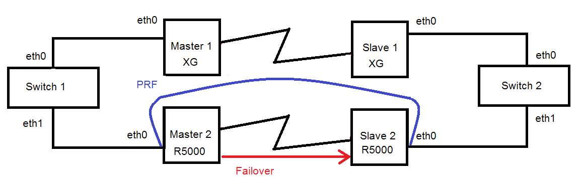
Redundancy of the radio link using XG using Infimux switches or devices from the R5000 series (Failover)
Description
Infinet R5000 devices have a functional redundancy of the channels. A hot standby might be created by using the Failover option. The Failover option does not depend on the method of data transmission on the main channel.The only condition is connectivity at level 2 between Infinet devices through both links.
The principle of operation is extremely simple. The Infinet device, on which the Failover option is configured, checks the availability of a specific MAC address through the primary link. If this MAC address is available, then the operation of the backup channel is blocked. The radio module stops broadcasting on the backup master. The standby slave device only listens to the radio while there is no signal from the master. Thus, the backup link can operate on the same frequency as the main one, but it does not have any influence on it. As soon as the monitored MAC address disappears in the main link, the backup link will be unlocked and traffic will begin to be transmitted over it. The process is completely automatic. However, the transition to a backup link is associated with a short-term idle time. Traffic will return automatically to the primary link as soon as the monitored MAC address appears in the primary link.
You can provide the redundancy for the link via XG devices with using R5000 devices.
Example
Attention
STP protocol may block correct working Failover option. Failover option causes short-time loops in one broadcast domain.
Configure first radio link
Configure second radio link
Create united MINT domain
Configure switch groups
Turn on the failover option
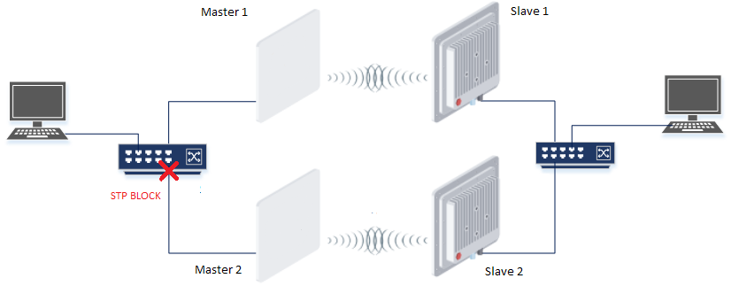
Redundancy of the radio link based on STP
Description
Infinet XG devices do not have software functionality for redundant links. However, you can create two redundant links on them with using third-party devices based on public technologies.
The simplest scheme will be the organization of two links established at the 2 level of OSI via two XG devices. STP protocol excludes loops. The traffic will be transmitted through one of the links, but if it breaks, it will go to the next one.
Unfortunately, in this case, the use of one frequency for two pairs of devices is not desirable.
Example
- Configure first radio link
- Configure second radio link
- Configure STP (not included in the example)
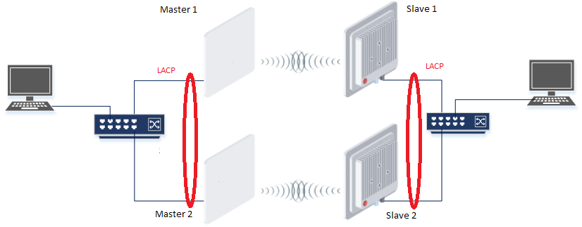
Redundancy of the radio link based on LACP
Description
Infinet XG devices do not have software functionality for redundant links. However, you can create two redundant links on them with using third-party devices based on public technologies.
The simplest scheme will be the organization of two links established at the 2 level of OSI via two XG devices. LACP protocol excludes loops and allows to increase throughput.
Unfortunately, in this case, the use of one frequency for two pairs of devices is not desirable.
Example
Configure first radio link
Configure second radio link
- Configure LACP (not included in the example)
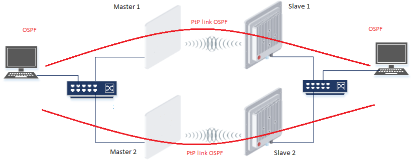
Redundancy of the radio link based on OSPF
Description
Infinet XG devices do not have software functionality for redundant links. However, you can create two redundant links on them with using third-party devices based on public technologies.
The simplest scheme will be the organization of two links established at the 3 level of OSI via two XG devices. OSPF protocol excludes loops and allows to increase throughput.
Unfortunately, in this case, the use of one frequency for two pairs of devices is not desirable.
Example
Configure first radio link
Configure second radio link
- Configure OSPF (not included in the example)