Introduction
This document is intended to demonstrate InfiNet Wireless devices potential performance. The data used in the document is obtained through laboratory testing. The parameters of communication channels in real conditions may differ from the presented, however, under conditions of minimal external influence, the obtained values are achievable in practice.
The link quality parameters depend on two factors: external conditions and wireless devices configuration. An environmental factors are a set of characteristics related to the formation, distribution and reception of a radio signal, the mounting quality, etc. The complex influence of these factors is unique and depends on the specific case, therefore the task of reproducing the possible situations diversity is time-consuming. The modulation code scheme decreasing is a consequence of signal-to-noise ratio (SNR) decreasing. Therefore, the possible influence of external factors during laboratory testing was taken into account in the initial data. The wireless networking fundamentals are detaily described in the corresponding online course available on the IW Academy portal.
The parameter configuration influence will be described within this document. The article contains several InfiNet Wireless hardware platforms, characteristic set of parameters that affect the performance will be specified for each.
Factors which determines channel characteristic
The modulation code scheme
The selected modulation code scheme for data transmission determines the communication channel throughput. Let's look at the example (see Figure 1) to confirm the statment.
Let's look at the example, we will transmitt 6 bit of information - "100111". In the first case, for the information sequence transmission, we will use the QPSK 3/4 modulation code scheme, in the second case - QAM16 1/2. The parity check code is used as the error-control code.
At the Figure 1 signal constellations for modulation code schemes QPSK 3/4 and QAM16 1/2 are shown. Each point corresponds to a certain amplitude value (A) and phase (p) of the signal, and a set of bits is assigned to each of these signals. By forming a signal with given amplitude and phase values, the corresponding data set is transmitted, and the set of all signals (constellation points) is called allowed states. The greater the number of allowed states, the more bits can be transmitted by a signal element with given amplitude and phase characteristics.
When using QPSK 3/4 modulation, each three bits information sequence will be complemented by one bit of parity check, those instead of the original six bits sequence, eight bits will be transmitted - "10011111". The allowed signal states number for QPSK modulation is four (22), therefore, one signal per unit of time (signal element) can transmit two bits of an error-control sequence. Thus, to transmit eight bits of the received sequence, four signal elements (8/2 = 4 signal elements) are required.
For QAM16 1/2 modulation, each information bit is complemented by one parity check bit — the original six-bit sequence is converted to a 12-bit sequence "110000111111". The allowed signal states number for QAM16 1/2 modulation is sixteen (24), therefore, one signal per unit of time (signal element) can transmit four bits of an error-control sequence. Thus, to transmit twelve bits of the received sequence, three signal elements (12/4=3 signal elements) are required.
Thus, six bits of the original information sequence using QPSK 3/4 were transmitted in four time slots, and using QAM16 1/2 - in three, this demonstrates the QAM16 1/2 modulation code scheme advantage in channel and information rate. The high modulation code schemes using can improve the communication channel performance by increasing the throughput, however, as it is shown in the online course, the high modulation code schemes using is possible only for radio channels with a large link margin.
In the R5000 family devices, the modulation code scheme type is shown as a bitrate, in the XG family devices, MCS itself is displayed. In order to eliminate confusions, in the document below the MCS (modulation code scheme) index will be used. The correspondence between modulation and index is shown in the table below.
Table of the correspondence between modulation code scheme and bitrate in R5000 devices
| Band, MHz | 5 | 10 | 20 | 40 | |
|---|---|---|---|---|---|
| Modulation code scheme index | Modulation type | Bitrate, Mbps | |||
| MCS15 | QAM64 5/6 | 32000 | 65000 | 130000 | 300000 |
| MCS14 | QAM64 3/4 | 29000 | 58000 | 117000 | 270000 |
| MCS13 | QAM64 2/3 | 26000 | 52000 | 104000 | 240000 |
| MCS12 | QAM16 3/4 | 19000 | 39000 | 78000 | 180000 |
| MCS11 | QAM16 1/2 | 13000 | 26000 | 52000 | 120000 |
| MCS10 | QPSK 3/4 | 9000 | 19000 | 39000 | 90000 |
| MCS9 | QPSK 1/2 | 6000 | 13000 | 26000 | 60000 |
| MCS8 | BPSK 1/2 | 3000 | 6000 | 13000 | 30000 |
Table of the correspondence between MCS index and modulation type in XG devices
| Modulation code scheme index | Modulation type |
| MCS10 | QAM1024 8/10 |
| MCS9 | QAM256 30/32 |
| MCS8 | QAM256 7/8 |
| MCS7 | QAM256 6/8 |
| MCS6 | QAM64 5/6 |
| MCS5 | QAM64 4/6 |
| MCS4 | QAM16 3/4 |
| MCS3 | QAM16 1/2 |
| MCS2 | QPSK 3/4 |
| MCS1 | QPSK 1/2 |
| MCS0 | QPSK 1/4 |
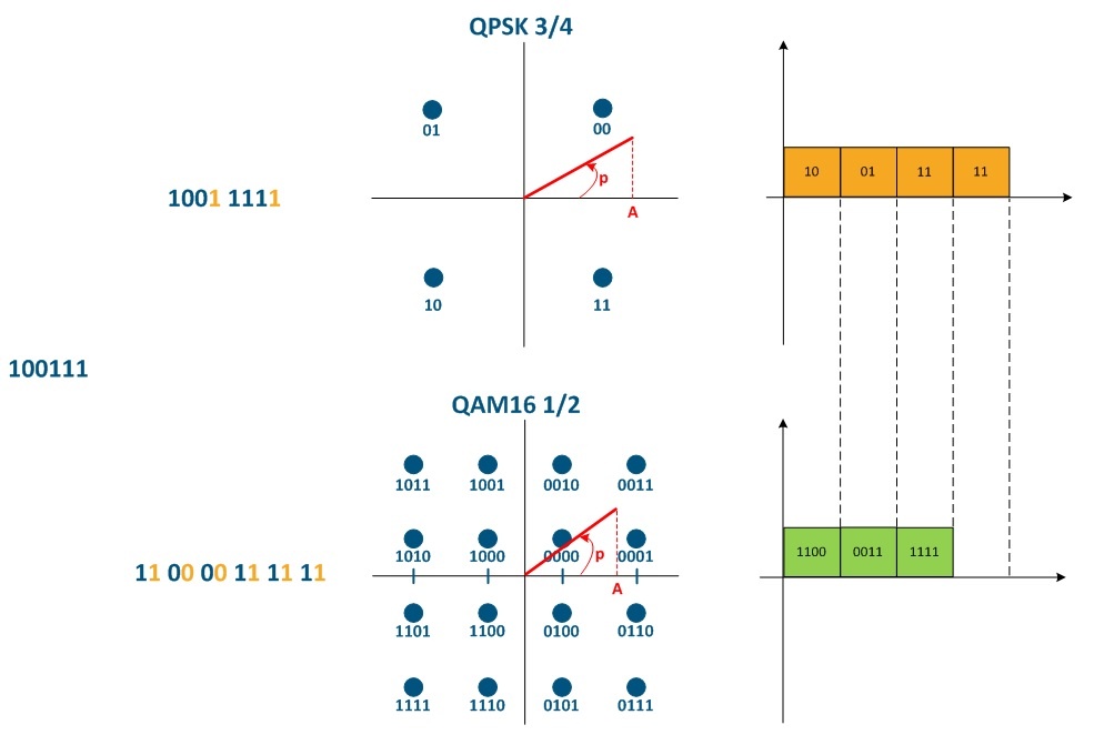
Figure 1 - The impact of the modulation code scheme on the communication channel throughput
Frame size
In practice, at the same time, multiple frames of different length are transmitted in the network, so it is useful to evaluate the link quality parameters by generating traffic consisting of frames with a given size. Testing is performed for frames with sizes from 64 to 1518 bytes, which is regulated by the Ethernet protocol.
To explain the frame size effect on the useful throughput of the communication channel, let's look at the Ethernet frame structure (see Figure 2a). An Ethernet frame consists of two service fields with constant length: a header (14 bytes) and a checksum field (4 bytes), and a data field (46-1500 bytes), i.e. total frame size is in the range of 64-1518 bytes.
Let's look at the task in which we need to transfer 1500 bytes of information by placing the data in Ethernet frames. In order to do this we will use frames of different lengths: 1518 bytes (Figure 2b), 518 bytes (Figure 2c), 268 bytes (Figure 2d). Summary information about the service headers size and its share in the data stream is given in the table below. We can see that with decreasing frame size, the cost of transmitting service headers significantly increases, while the share of payload data decreases.
| Frame size | Total frames size | Headers size | Share of headers |
|---|---|---|---|
| 1518 bytes | 1518 bytes | 18 bytes | 1.19% |
| 518 bytes | 1554 bytes | 54 bytes | 3.47% |
| 268 bytes | 1608 bytes | 108 bytes | 6.72% |
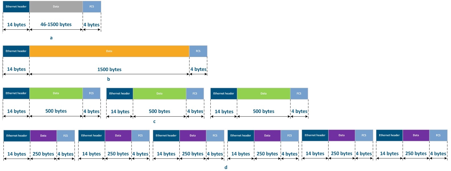
Figure 2 - Ethernet frame structure: a - general structure, b - frame with 1500 bytes data field, c - frames with 500 byte data fields, d - frames with 250 byte data fields
With decreasing frame size, the share of overhead costs for service headers (regulated by the requirements of the data transfer protocol, as shown in the table above) increases. The solution for improving the efficiency of data transfer by using maximum length frames seems obvious. However, small frames are processed faster by network equipment, it reduces the time to propagate a frame from source to destination. Distribution time is critical parameter for some types of traffic. For real-time traffic, such as voice traffic, a reduction in frame size is forced, because the key indicator of the link quality in this case is not the throughput, but the delay value. Therefore, the data should be sent as quickly as possible, in smaller portions.
In general, the delay value depends on:
- the radio signal propagation time (depends on the propagation medium);
- frame processing time (depends on the device's packet performance);
- time spent in the queue (depends on the link loading level, the size of the device memory buffers and QoS configuration).
Ширина частотного канала
При установке радиоканала между двумя устройствами, для них выбирается несущая частота F1, спектр которой представлен на рисунке 3а. Такой сигнал не несёт информации, поскольку его основные параметры (амплитуда, частота, фаза) известны и неизменны, т.е. можно предсказать состояние сигнала в любой из будущих периодов времени. Для того, чтобы радиосигнал стал носителем информации, его параметры изменяют в соответствии с потоком данных. Этот процесс называется модуляцией. В процессе модуляции изменяются основные параметры сигнала и преобразуется его спектр - теперь сигнал занимает определённую полосу частот ΔF (см. рисунок 3б).
Следует заметить, что ширина частотного канала влияет на доступный набор модуляционно-кодовых схем и, как следствие, на производительность канала. Таким образом, увеличение пропускной способности радиоканала может быть доступно с помощью расширения занимаемой полосы частот.

Рисунок 3 - Спектр сигнала: а - несущая частота, б - модулированный сигнал
Размер радиокадра
Для пояснения влияния размера радиокадра на параметры качества канала связи рассмотрим соединение двух устройств (XG или R5000 с прошивкой TDMA). Механизм передачи информации в радиосреде представлен ниже (см. рисунок 4). Подробное описание механизмов передачи данных при TDMA и Polling представлено в TDMA и Polling: особенности применения в беспроводных сетях. Под радиокадром понимается период времени, в рамках которого выполняется обслуживание сектором одного абонентского устройства. В течение одного радиокадра происходит обмен данными между двумя устройствами в нисходящем и восходящем потоках.
Аналогично кадрам Ethernet часть радиокадра отдана под служебные нужды. В частности, обязательными являются поле синхронизации и защитный интервал (guard interval), которые не зависят от размера радиокадра. Оставшееся время передаются полезные данные. Таким образом, аналогично кадрам Ethernet, большее значение длины радиокадра приведёт к более эффективной утилизации канала связи, однако вместе с этим увеличится величина задержки (следующий пакет данных может быть передан только в следующий интервал передачи, а чем больше длина радиокадра - тем больше время ожидания).

Рисунок 4 - Механизм передачи данных при TDMA и TDD
Дальность связи
Параметр "Максимальное расстояние" влияет на величину защитного интервала guard (см. рисунок 4), а значит на эффективность использования пропускной способности канала связи. Кроме того, фактическая дальность расположения абонентской станции влияет на время распространения радиосигнала в среде.
Число абонентских станций
Дополним рисунок из раздела "Длительность радиокадра", добавив ещё два абонентских устройства (см. рисунок 5).
Время ожидания передачи пропорционально числу абонентских станций, т.к.для обмена данными с каждой станцией выделяется временной интервал, равный длине радиокадра. Таким образом, величина задержки зависит от числа активных абонентов.

Рисунок 5 - Механизм передачи данных при TDMA для трёх абонентских станций
Набор фирменных параметров
Опция Greenfield
Опция Greenfield устанавливается как на устройствах Master, так и на Slave и отвечает за включение оптимизации служебной информации, передаваемой через радиоканал. Оптимизация позволяет существенно снизить объём служебной информации и улучшить производительность на 10-15% за счёт увеличения объёма полезных данных в радиокадре.
Опция VBR
Оция VBR (variable bitrate - переменный битрейт) устанавливается на ведомом устройстве и позволяет повысить эффективность при передаче служебных данных. При отключенной опции VBR служебные поля сообщений Sync передаются с использованием минимальной модуляционно-кодовой схемы. При активации VBR, поля Sync будут передаваться на модуляционно-кодовой схеме выше минимальной, если есть такая возможность. Это позволит передать синхропоследовательность быстрее, что снизит долю служебных сообщений в общем времени передачи и повысит производительность канала связи.
Опция VBR доступна только на устройствах семейства R5000 с ПО, поддерживающим технологию TDMA.