Abbreviations
The following abbreviations are used in this document:
- IP – Internet Protocol
- MINT - Mesh Interconnection Networking Technology
- PRF – Pseudo Radio interface
- OSPF – Open Shortest Path First
- RCMD – Remote Command
Purpose of this document
InfiNet Wireless is one of the leading manufacturers of Broadband Wireless Access equipment for carrier grade fixed installations. InfiNet Wireless uses its own proprietary transport protocol – MINT which interconnects units by wireless and wired (MINT-over-Ethernet technology provides MINT connectivity over wired Ethernet) links. Within MINT areas, it is possible to send any command via the MINT protocol to a specified unit for execution (MAC address can be used for specific unit selection or broadcast MAC addresses can also be used)
This document shows how units management can be organized using MINT protocol. MINT protocol operates on both Layer 2 and Layer 3. However, in case incorrect or missing IP settings on the units, the management configuration on InfiNet Wireless unit can be restored by issue of MINT RCMD (remote commands) from another InfiNet Wireless unit. MINT management only required L2 and MINT connectivity between units.
Introduction to MINT protocol
MINT – Mesh Interconnection Network Technology
MINT main purpose is to provide path selection with best quality for wireless (and wired) traffic on Layer 2 (switched traffic).
MINT highlights
| Path quality check | MINT constantly checks transmission quality for each link. In case of link degradation MINT quickly changes some parameters in order to keep packet loss value as low as possible automatically. In case of redundant links available, MINT will switch main traffic flow path to link with better transmission quality. |
| Predictive model | MINT supports predictive model to select the best path in advance, in order to deliver data as quickly as possible. |
| Redundancy and load balancing | MINT protocol was designed to work with multiple redundant paths. Moreover, such redundancy can be used for load-balancing to utilize all available connections from one customer point to another. |
| Minimum time for data delivery | MINT main criteria for optimal path selection is time (minimal packet delivery time). |
| MINT connections via wired Ethernet (MINT-over-Ethernet) | MINT-over-Ethernet is unique feature of IW, allows to select best path through network including wired interfaces. Thus, both wireless and wired interfaces would be utilized. MINT-over-Ethernet can be enabled to provide backup and redundant paths, especially for mobile projects. Pseudo Radio Interface (PRF) are virtual interfaces created on base of Ethernet interfaces provides MINT-over-Ethernet. |
| Switching loop prevention | MINT has built-in mechanism to prevent data from looping within MINT network (when redundant paths are present). |
MINT position
MINT link is the link between two units, which use MINT as transport protocol between each other.
MINT encapsulates and transports through MINT link (or links) all traffic and all protocols. Thus, MINT is the only one transport protocol for IW R5000 family products.
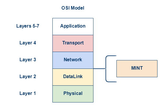
MINT operates between DataLink and Network Layers of the OSI Model. Therefore MINT is capable to encapsulate and carry through link Layer 2 traffic (Ethernet switched data) and Layer 3 traffic (IP routed data).
MINT technology overview
Where MINT is available
Only adjacent neighbor connectivity is needed to create MINT powered link:
- For radio interfaces MINT is enabled by default, only radio parameters should be configured;
- For Ethernet interfaces MINT-over-Ethernet should be enabled manually (disabled by default) for Ethernet interfaces. In case to perform it Pseudo-radio interface (PRF) should be created. Each BS and CPE supports such interfaces.
MINT path selection
In case of multiple MINT routes the protocol would always choose one route for single data frame and would have possibility to re-select new route for another data frame in case of any path characteristics change. Path characteristics are described by aggregated parameter MINT cost.
MINT cost is calculated from the following parameters:
- Signal-to-Noise Ratio (for connectivity over radio interfaces);
- Throughput or Bitrate (for connectivity over radio interfaces);
- Percentage of retries ;
- Link load and throughput;
- Some other parameters.
Link quality assessment:
- Each MINT unit has full MINT map with all MINT neighbors;
- Each MINT neighbor constantly checks MINT cost between each other;
- Each check is to be done each 1-3 s;
- MINT path can be predictably changed due to change in link quality (cost drop).
Loop free capability:
- The path for data frame is selected by the lowest overall cost;
- The predefined path is set for every packet, unless any changes in network;
- The path for frame or packet can be different;
STP BPDU transmission can be blocked in configuration through any logical interfaces.
MINT path selection capabilities
MINT protocol will quickly adjust to possible changes in critical parameters – re-calculate MINT cost for each path and rebuild the path accordingly. Moreover, due to built-in capability to quickly adopt changes, even data flow path within MINT network can change rapidly too.
On the picture below shown mesh topology of units. All units run MINT protocol for each interface, hence each connection is handled by MINT protocol. In this case, node J has to send data to node F.
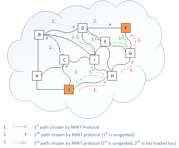
Red path (1st path) has been chosen by MINT protocol initially.
Blue path (2nd path) – MINT decides to switch to 2nd path due to congestion between node H and
node G.
Green path (3rd path) – MINT decides to abandon 2nd path too due to excessive traffic load and switch traffic flow to 3rd path.
Each decision to change active traffic path can take place every 1-3 seconds depends on MINT protocol settings for every unit.
MINT area
All benefits of MINT protocol mentioned above, would be active only in network there all units supports MINT protocol as the only one transport protocol. Such MINT network is called MINT area. Thus it is required to create unified MINT area consisting of InfiNet Wireless units interconnected by wireless radio interfaces (RF) or by wired MINT-over-Ethernet (Pseudo Radio) interfaces.
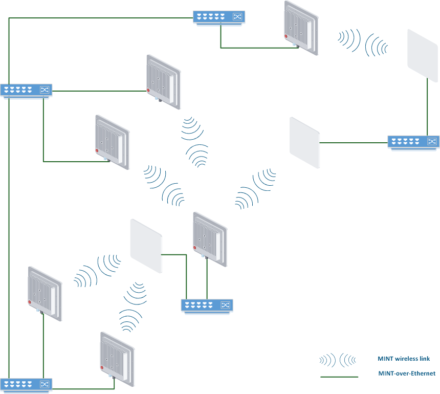
Next section contain logical interconnection scheme with RF and PRF links for current physically (wired and wireless) connected units (MINT connections logical scheme).
MINT connections logical scheme
Wireless connection is represented by red link on logical interconnection scheme, wired PRF links are shown in green color.
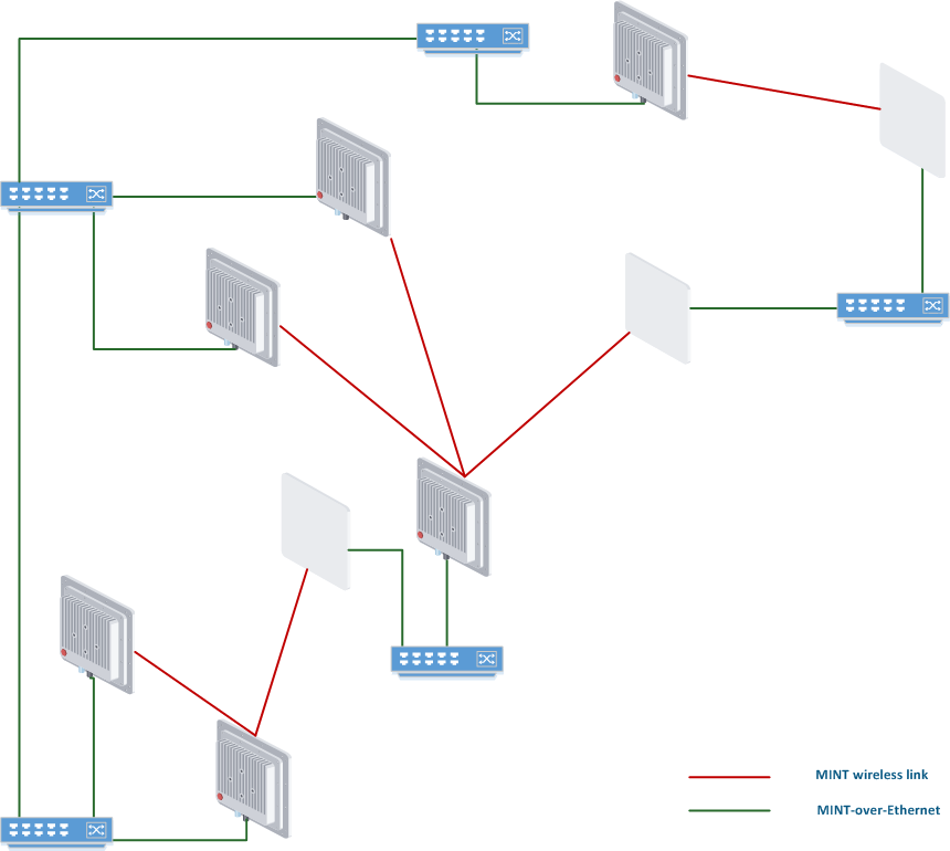
So, here we have network where almost each unit has at least two connections via MINT protocol. Therefore, it is possible to balance traffic via one or second path (or even load balance using both). In case of one link failure, traffic will flow through the another one. Eventually, under certain circumstances the units can always stay connected because both links down situation is very unlikely to happen. It doesn’t really matter what type of physical connection is used (wired or wireless), MINT use any connection. The only difference is MINT cost value for each link.
MINT RCMD
Within MINT area every MINT node can receive information about another MINT node through its MINT neighbors. Every MINT neighbor exchanges information about its adjacent links, their quality, load, issue and MAC address. MAC address is used as identification label for MINT node.
List of MINT neighbors:
Master#console>mint map detail

==============================================================================
Interface rf5.0  TDM (5 ms DL/UL:Auto) (RSSI=-43 Dist=1) (Sync Off)
Node  00043513724F  "Master", Id 25871, Nid 0, (Master)
Freq 5470, Band 20, Sid 10101010, autoBitrate 130000 (min 13000), Noise -94

 ------- ---------------------------- ------------ -----  ------- ----- -------
   Id         Name                        Node     Level  Bitrate Retry Options
 ------- ---------------------------- ------------ rx/tx   rx/tx  rx/tx -------
   60755 Slave                        00043523FA93 14/14  104/104  0/0  /S/
	  load 0/4, pps 0/1, cost 51
	   pwr 25/27, rssi -57/-53, snr 33/36
	   dist 0.14
	   H11v2.1.11, IP=10.10.10.2, up 18 days
   60756 Slave 2                      00043523FA94 18/30  117/130  0/0  /S/
	  load 5/2, pps 2/0, cost 51
	   pwr 12.5/27, rssi -50/-21, snr 41/63
	   dist 0.18
	   H11v2.1.11, IP=192.168.103.37, up 14 days
 ------- ---------------------------- ------------ -----  ------- ----- -------
 2 active neighbors
 Total load: 5/6 (rx/tx), 11 (sum) Kbps
 Total nodes in area: 3
So, MINT neighbor is designated by MAC address.
Unique feature of MINT protocol is possibility to send any command to any MINT neighbor for execution at MINT neighbor unit. It is called MINT Remote Command execution (RCMD). MINT RCMD could be helpful in lots of cases, such as: lost password, ip address settings cleared, no possibility to login to remote MINT neighbor directly, it is required to execute some commands on all MINT neighbors.
Examples
Force reboot on remote MINT neighbor Master#mint rf5.0 rcmd -n 00043523FA93 "restart yes" |
Set new IP address and Default Gateway on remote MINT neighbor Unknown node#2> mint rf5.0 -rcmd -node 000435130AD8 "ifc svi1 172.12.77.2/27; route add 0.0.0.0/0 172.12.77.1;" |
NOTE
Full syntax of MINT RCMD command with different options has detailed description in WANFleX command reference guide Layer 2 commands set -PHY and MAC.
MINT area prerequisites
In default configuration MINT protocol is enabled and used only between wireless radio interfaces. However, in order to create interconnected (by MINT protocol) MINT area MINT-over-Ethernet interfaces (PRF) are required.
In order to enable MINT-over-Ethernet it is required to:
- Create virtual Pseudo Radio Interface (PRF). PRF can be created as logical sub-interface for plain Ethernet interface (parent interface) , or as logical sub-interface for another logical interface (for example, VLAN interface can be used as parent interface for PRF);
- Start MINT protocol for PRF interface;
- JOIN command connects internal bonds between MINT areas behind Radio interfaces and PRF interfaces.
Within the same Ethernet broadcast domain (LAN) two (or more) IW units with PRF interfaces created, with MINT protocol started can find and establish communication via MINT protocol by sending and receiving Ethernet broadcasts initially. Thereafter, IW units will use Ethernet unicast data transfer.
VLAN considerations
In case two IW are placed within certain VLAN, then configuration of PRF should be corrected with certain VLAN tag. Please pay attention that default configuration (or template part) should exactly use the relevant VLAN tag number.
MINT-over-Ethernet & VLANs
MINT-over-Ethernet does generate broadcast traffic to detect and find other MINT neighbors. Sometimes, such broadcast traffic could be treated as abnormal for network, especially for enterprise networking with comprehensive network security policy.
NOTE
It is recommended to segment MINT-over-Ethernet connections into dedicated VLAN zones, thus keeping all broadcast traffic within unique VLAN
Moreover, in vast MINT-over-Ethernet network different MINT-over-Ethernet areas should be isolated from each other in order to provide complex traffic engineering or prevent undesired traffic path selection. Hence, VLAN separation should be used in such cases.
Configuration part
Steps to configure MINT-over-Ethernet
Only step 1 is different for untagged approach (1a) and for vlan based approach (1b)
CLI based configuration
1a. Create Pseudo Radio (PRF) interface for untagged interconnection