Wireless device
An integrated wireless device contains the radio and networking electronics. Implemented in a robust all-weather metal enclosure, this equipment can be used to create point-to-point wireless links at distances in excess of 5 km (depending on weather conditions, interference, terrain, climate zones, etc.). The following lens-type integrated antenna with an antenna gain 39 dBi is available.
Grounding bolt
For grounding the ODU to the supporting structure.
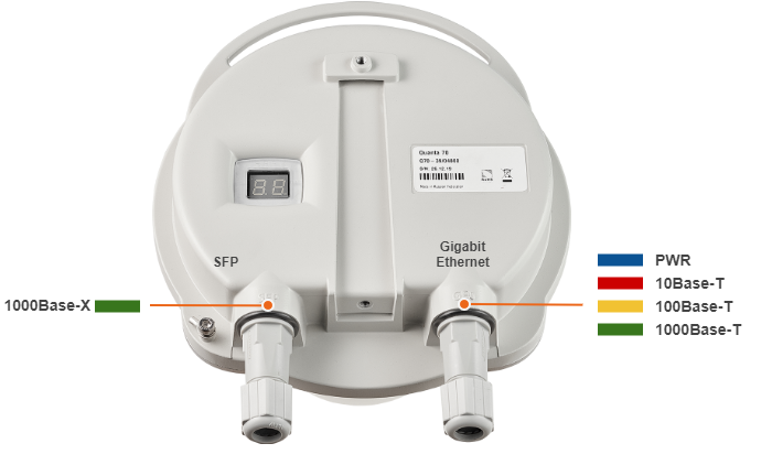
Wired interfaces
- Gigiabit Ethernet Port - RJ45 socket for connecting to power supply and network via the PoE power supply. The network connection to the ODU is made via a 1000BaseT (Gigabit) Ethernet connection. Power is provided to the ODU over the 1000BaseT Ethernet connection using a standard IEEE 802.3at passive PoE power supply.
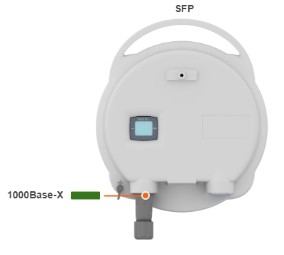
- SFP Port - external optical Gigabit port for plugging of the optical SFP transceiver module.
RSSI level Indicator
RSSI value indication in dBm.
Power, wired and wireless statuses indication
Power, wired and wirelesses statuses indication is performed via glassy plug of the cable gland.
Initialization stage
| Ports | Condition | Indication |
|---|---|---|
GE0 SFP | Power On (initialization) | The LEDs on both ports light up with white on second. Then LEDs check is performed: red, blue, green are lightened up sequentially. |
| Power On (loading) | At the beginning green is lightened a few seconds, on the second loading stage switches to blue. | |
| ERP stage | Port (GE0 or SFP) with established link lights up with green, the second port remains blue. |
Working stage
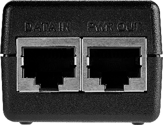
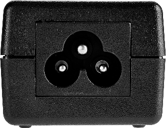
Power Supply
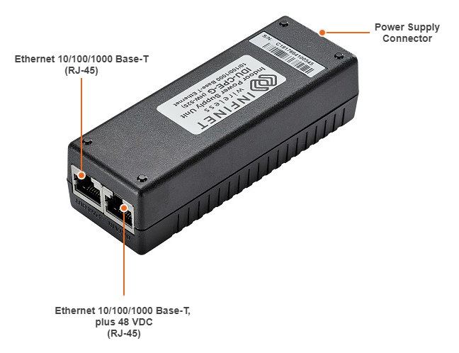
Indoor Gigabit PoE Injector with lightning protection IDU-CPE-G.
| Parameter | Description | ||||||||||||||||||||||||||||||||||||||||
|---|---|---|---|---|---|---|---|---|---|---|---|---|---|---|---|---|---|---|---|---|---|---|---|---|---|---|---|---|---|---|---|---|---|---|---|---|---|---|---|---|---|
| Size | 110*40*30 mm (L*W*H) | ||||||||||||||||||||||||||||||||||||||||
| Weight | 0,110 kg | ||||||||||||||||||||||||||||||||||||||||
| Connectors and Interfaces |
| ||||||||||||||||||||||||||||||||||||||||
| Supported Ethernet Modes |
| ||||||||||||||||||||||||||||||||||||||||
| Input Power Requirements |
| ||||||||||||||||||||||||||||||||||||||||
| Consumption |
| ||||||||||||||||||||||||||||||||||||||||
| Operating temperature range |
| ||||||||||||||||||||||||||||||||||||||||
| Operating humidity |
| ||||||||||||||||||||||||||||||||||||||||
| Storage temperature |
| ||||||||||||||||||||||||||||||||||||||||
| Storage humidity |
| ||||||||||||||||||||||||||||||||||||||||
| Output Power Voltage |
| ||||||||||||||||||||||||||||||||||||||||
| Ethernet Connectors Pin-out |
| ||||||||||||||||||||||||||||||||||||||||
| Electromagnetic Emission & Immunity |
| ||||||||||||||||||||||||||||||||||||||||
| Regulatory Compliance |
| ||||||||||||||||||||||||||||||||||||||||
| Safety |
| ||||||||||||||||||||||||||||||||||||||||
Lightning protection unit
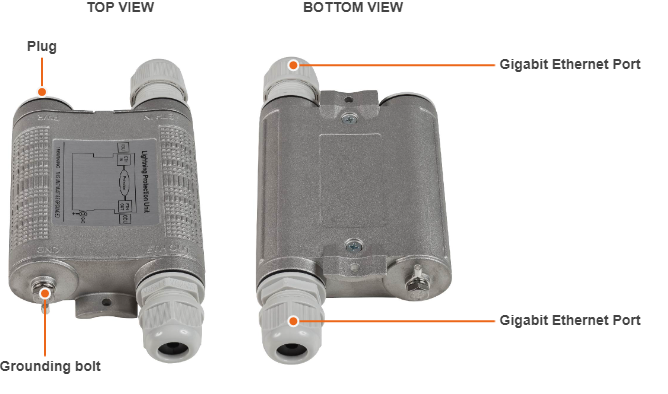
Optional indoor/outdoor Lightning Protection Unit for Infinet Wireless systems designed to withstand the toughest conditions and protect the outdoor or the indoor unit from sudden power surges induced by lightning strikes. It provides the same level of protection as AUX-ODU-INJ-G. AUX-ODU-LPU-G is compatible with all Infinet Wireless devices.
Despite the fact every Infinet Wireless unit has a built-in lightning protection, AUX-ODU-LPU-G, thanks to its superior GR-1089-grade protection, greatly reduces the risk of replacing damaged devices operating in harsh environments or difficult-to-reach locations.
NOTE
The device is not supplied by default and must be ordered separately.
| Parameter | Description | ||||||||
|---|---|---|---|---|---|---|---|---|---|
| Size and Weight |
| ||||||||
| Connectors and Interfaces |
| ||||||||
| Supported Ethernet Modes |
| ||||||||
| Water and Dust Protection |
| ||||||||
| Operating temperature range |
| ||||||||
| ETH IN and ETH OUT pin-out | Pin | 1 | 2 | 3 | 4 | 5 | 6 | 7 | 8 |
| Data pair | A+ | A- | B+ | C- | C+ | B- | D+ | D- | |
| Lightning Protection | In compliance with:
| ||||||||
Packing list
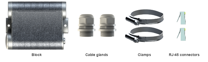
AUX-ODU-LPU-G is supplied with a worm clamp TORRO 40-60/9 C7 W4 DIN 3017 - 2 pcs. The clamp is made of stainless steel A4, width 9 mm, allows the installation on a mast with a diameter of 35 to 60 mm. In case of mast diameter more than 60 mm, a similar clamps (up to a 230 mm diameter) with a width of up to 12-13 mm can be used.
Part number description
Quanta 70 part number has the following structure

Structure items are described below
| Item | Description |
|---|---|
| 1 | Product family name:
|
| 2 | Frequency range:
|
| 3 |
|