General recommendations
- It is recommended to have two teams prepared for alignment procedure, each team with at least two members: one should take the signal readings and communicate with the remote end, the other should manipulate the antenna.
- For rough alignment use the azimuth, elevation angle and suspension height from InfiPLANNER report.
- On the device case there is a RSSI value in dBm indicating the received signal level.
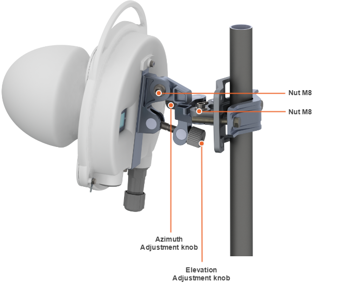
- For antenna alignment use adjustment knobs of the MONT-KIT-85PW. After adjustment tighten nuts M8.
NOTE
For further adjustment if needed weaken the nuts M8 on about 15 degrees. Perform required antenna alignment and then tighten nuts M8.
Do not adjust knobs without weaken the nuts first.
- For more accurate alignment, use the alignment tool built into the device web interface.
- After the initial alignment, the device at the remote side must be fixed. Firstly, the alignment is performed for one device, then for another.
Alignment tool
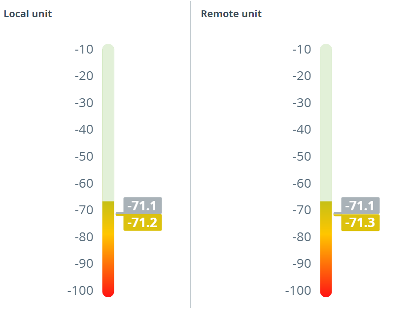
Use the Alignment tool to point and optimize the antenna in the direction of maximum link signal. The built-in graphical antenna alignment tool displays the signal levels for both devices, this makes an alignment process fast and accurate.
A green marker indicates the current signal level. To achieve the best performance, this marker should be as close as possible to the gray area values, which displays the maximum calculated value possible for this link. A gray marker indicates the maximum value that was reached on this channel.