Table of content
Description
RIP (Routing Information Protocol) - a dynamic routing protocol based on the Bellman-Ford algorithm. The protocol has the following features:
- first RIP version was developed in 1969, described in RFC 1058;
- second RIP version was developed in 1994, described in RFC 2454.This version is the main one for use in IPv4 networks. There is no backward compatibility between the first and second versions;
- there is a RIP version developed for IPv6 networks. This version is called RIPng and is described in RFC 2080;
- RIP is an internal distance vector routing protocol;
- the number of hops is used as a metric, i.e. the routers number at the path to the destination network. The maximum metric value is 16, it limits the network size where RIP can be used;
- the multicast address 224.0.0.9 is reserved for RIP version 2. The first version of the protocol uses the broadcast address 255.255.255.255;
- UDP datagrams are used for service information transmission, port 520 is assigned to the protocol;
- the first RIP version only supports the routes to classful networks distribution, the second to classless;
- distance value 120 is used for RIP;
- RIP supports authentication: routing information will only be accepted from a router with the same the key value.
RIP operation algorithm
Let's look at the example routing information distribution over a network using RIP. The example includes the following scheme (Figure 1):
- the network consists of four routers R1, R2, R3 and R4, connected as a ring, they forms a RIP domain. A RIP domain is a set of routers that exchange routing information using RIP;
- router R1 has an external link to the WAN-1 network;
- an independent IP network is assigned for each link.
RIP must be configured on all routers. WAN-1 is the external network, i.e. the route to this network must be added to the RIP domain as external.
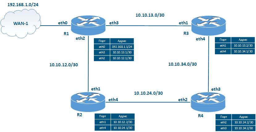
Figure 1 - Network scheme to explain RIP operation principles
In this example, routing information distribution from router R1 will be described, routes from other devices will be distributed in the same way.
The RIP operation algorithm in the described scheme is following:
- Start RIP.
- Routing information distribution.
- Adding routes to RIB.
- Adding routes to FIB.
- Timers control.
- Network changes control.
Start RIP
At this stage, the RIP must be enabled on the routers and must be defined the list of interfaces that will participate in the RIP operation.
The list definition is done using the "network A.B.C.D/M" command. All network interfaces which IP addresses belong to the specified range participate the RIP. This means that routing information will be distributed from these interfaces, and information about the networks associated with these interfaces will be transmitted to other routers.
If an interface participates the RIP, but routing information should not be distributed over that interface, then the interface can be configured as passive.
Let's assume that the commands "network 10.10.13.0/30" and "network 10.10.12.0/30" have been executed on router R1. In this case, the router will assume that RIP is running on eth2 and eth3.
Routing information distribution
The routing information distribution about the networks connected to router R1 is performed in the following sequence:
- Step 1: router R1 generates service messages with routing information. Service messages contain information about networks 10.10.13.0/30 and 10.10.12.0/30, since the interfaces associated with these networks are included in RIP at the protocol starting stage. Also, service messages include information about the 192.168.1.0/24 network, since router R1 must redistribute external routes according to the task conditions. The metric value for each network is set to 1.
- Step 2: the router sends out the service messages generated at step 1 (Figure 2a). Distribution is performed through the eth2 and eth3 interfaces included in the RIP at the protocol starting stage.

Figure 2a - R1 routing information distribution
- Step 3: routers R2 and R3 generate service messages to transmit routing information to router R4:
- R2: the router includes in the service message the 192.168.1.0/24 and 10.10.13.0/30 networks received from router R1, incrementing the metric value. Information about the 10.10.12.0/30 network received from R1 is ignored because R2 is directly connected to this network. Instead, router R2 includes the 10.10.12.0/30 network with metric 1 in the service message, announcing the network by itself. Also, the service message includes information about the network 10.10.24.0/30.
- R3: the router includes in the service message the 192.168.1.0/24 and 10.10.12.0/30 networks received from router R1, incrementing the metric value. Information about the 10.10.13.0/30 network received from R1 is ignored because R3 is directly connected to this network. Instead, router R3 includes the 10.10.13.0/30 network with metric 1 in the service message, announcing the network by itself. Also, the service message includes information about the network 10.10.34.0/30.
- Step 4: routers R2 and R3 send the service messages formed in the previous step to router R4 (Figure 2b). Note that R2 and R3 send routing information to R1, but this process will not be described in this example.

Figure 2b - Routing information distribution by routers R2 and R3
Adding routes to RIB
After exchanging service messages, the routers add the received routes to the RIB. In this case, some routes are filtered out. To filter the routing information, devices are guided by the following principles:
- only one route to the destination network can be added to the RIB;
- if there are two routes to the same network, a route with a lower metric value is added to the RIB;
- a route with a higher metric value can be added to the RIB if it is received from the same source;
- if there are two routes to the same destination network with the same metric values, then the route received first will be added to the RIB.
Let's assume that router R4 received a service message from router R2 earlier than from R3. Then, in accordance with the described principles, routes add the following routing information to the RIB:
| R2 router | ||
|---|---|---|
| Destination network | Metric | Gateway |
| 10.10.12.0/30 | 1 | - |
| 10.10.24.0/30 | 1 | - |
| 10.10.13.0/30 | 2 | 10.10.12.1 |
| 192.168.1.0/24 | 2 | 10.10.12.1 |
| R3 router | ||
|---|---|---|
| Destination network | Metric | Gateway |
| 10.10.13.0/30 | 1 | - |
| 10.10.34.0/30 | 1 | - |
| 10.10.12.0/30 | 2 | 10.10.13.1 |
| 192.168.1.0/24 | 2 | 10.10.13.1 |
| R4 router | ||
|---|---|---|
| Destination network | Metric | Gateway |
| 10.10.24.0/30 | 1 | - |
| 10.10.34.0/30 | 1 | - |
| 10.10.12.0/30 | 2 | 10.10.24.1 |
| 10.10.13.0/30 | 2 | 10.10.34.1 |
| 192.168.1.0/24 | 3 | 10.10.24.1 |
Adding routes to FIB
Routes export from RIB to FIB is go along with the analysis of distance values assigned to the route source. Distance value 120 is assigned to RIP, so some routes added to the RIB at the previous step will be filtered out. For example, all routes with metric 1 will be discarded because these are routes to directly connected networks and have 0 distance value.
Timers control
The routing information distribution described above is cyclically repeated. The repetition period is equal to the update timer value. By default the update timer is 30 seconds. Thus, all routing information on the network is distributed every 30 seconds.
Note, routers do not establish neighbor relations and do not synchronize the routing information exchange time, therefore, the time for sending service messages by routers is distributed in the 30 seconds interval, it helps to avoid service traffic bursts in the network.
After the route obtained via RIP is placed in the RIB, the timeout timer is started, by default its value is 180 seconds. If the router does not receive a route update within 180 seconds, the route will be marked as unavailable, i.e. the metric value of such a route is set to 16. The router cannot use this route for data transmission.
RIP service data exchange is not guaranteed, so the timeout timer value must be greater than the update timer. Otherwise, there may be false operation and determining routes as unavailable.
After adding a route to the RIB, in addition to the timeout timer, the garbage timer is also started with the default value 240 seconds. If the router does not receive a route update within 240 seconds, then such a route will be removed from the routing table.
Updating the routing information resets the timeout timer and garbage timer to their original values.
Network changes control
RIP is a dynamic routing protocol and must adapt to changes in the network. There are three scenarios of the changes:
- new link has been added;
- link is out of order;
- router is out of order.
New link has been added
Let's add a new link between router R1 and WAN-2 to the example scheme (Figure 3a). In this case, the WAN-2 network will be external for RIP, it means that the route to this network will be distributed similarly to the route to the WAN-1 network: router R1 will announce this network with metric 1, R2 and R3 will increment the metric value and transmit route to R4. АIn case of new routers included to the RIP domain the algorithm will be similar.
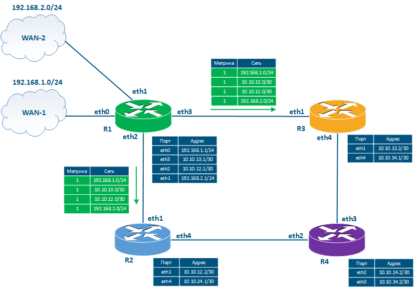
Figure 3a - The example of service messages sending when a new link has been added
Link is out of order
Let's assume that the link between routers R1and R3 fails (Figure 3b):
- Step 1: интерфейсы eth3 маршрутизатора R1 и eth1 маршрутизатора R3 перейдут в статус down.
- Этап 2: маршрутизаторы R1 и R3 установят в RIB маршруту к сети 10.10.13.0/30 значение метрики 16.
- Этап 3: в соответствии с истечением update timer, маршрутизаторы R1 и R3 сформируют служебное сообщение, включающее известную маршрутную информацию. В это сообщение включается путь к недоступной сети, причём метрика этого маршрута устанавливается равной 15.
- Этап 4: маршрутизаторы R2 и R4 получают служебные сообщения от R1 и R3, инкрементируют значение метрики и помещают маршрут в RIB. В RIB маршрутизаторов R2 и R4 уже есть маршрут к сети 10.10.13.0/30 с метрикой 2, но т.к. источниками новых маршрутов с худшей метрикой являются те же маршрутизаторы, то маршрут в RIB будет заменён на маршрут с метрикой 16. Таким образом все маршрутизаторы сети получат информацию о недоступности канала связи.

Рисунок 3б - Пример рассылки служебных сообщений при выходе из строя канала связи
Время, в течение которого распространяется обновлённая информация зависит от размеров сети и зависит от значения update timer. Учитывая, что максимальный размер сети - 16 хопов, а update timer по умолчанию равен 30 секундам, то в худшем сценарии время распространения информации о недоступности канала связи будет равно 15*30 = 450 секунд.
Выход из строя маршрутизатора
Дополним схему двумя коммутаторами SW1 и SW2 (рис. 3в) и рассмотрим сценарий выхода из строя маршрутизатора R1.
При выходе из строя маршрутизатора R1, он не успевает отправить обновление маршрутной информации о своей недоступности маршрутизаторам R2 и R3. Кроме того, R2 и R3 не узнают о недоступности R1, поскольку они непосредственно подключены к коммутаторам SW1 и SW2, которые не поддерживают работу протокола RIP. В этом случае, маршрутизаторы сети будут считать R1 доступным на протяжении timeout timer и будут использовать маршруты, связанные с R1. В частности, в таблице маршрутизации всех маршрутизаторов будут активны маршруты к сетям 10.10.12.0/30, 10.10.13.0/30 и 192.168.1.0/24.

Рисунок 3в - Пример рассылки сообщений при выходе из строя маршрутизатора R1
Возникновение ложных маршрутов
Упростим рассматриваемую схему, оставив два маршрутизатора R1 и R3 (рис. 4а). Будем считать, что маршрутизаторы обменялись маршрутной информацией и таблицы маршрутизации устройств находятся в актуальном состоянии.

Рисунок 4а - Схема сети для сценария возникновения ложных маршрутов
| Маршрутизатор R1 | ||
|---|---|---|
| Сеть назначения | Метрика | Шлюз |
| 10.10.13.0/30 | 1 | - |
| 192.168.1.0/24 | 1 | - |
| Маршрутизатор R3 | ||
|---|---|---|
| Сеть назначения | Метрика | Шлюз |
| 10.10.13.0/30 | 1 | - |
| 192.168.1.0/24 | 2 | 10.10.13.1 |
Пусть канал связи между маршрутизатором R1 и внешней сетью WAN-1 вышел из строя (рис. 4б). Маршрутизатор R1 устанавливает для такого маршрута метрику равную 16, однако не формирует служебное сообщение с обновлённой маршрутной информацией, т.к. значение update timer равно 25 секунд. В то же время update timer на маршрутизаторе R3 равен 3 секундам.
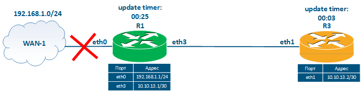
Рисунок 4б - Возникновение неисправности с каналом связи R1 - WAN-1
| Маршрутизатор R1 | ||
|---|---|---|
| Сеть назначения | Метрика | Шлюз |
| 10.10.13.0/30 | 1 | - |
| 192.168.1.0/24 | 16 | - |
| Маршрутизатор R3 | ||
|---|---|---|
| Сеть назначения | Метрика | Шлюз |
| 10.10.13.0/30 | 1 | - |
| 192.168.1.0/24 | 2 | 10.10.13.1 |
Через 3 секунды после выхода из строя канала связи R1 - WAN-1 истекает время update timer маршрутизатора R3, поэтому R3 отправляет обновление маршрутной информации маршрутизатору R1 (рис. 4в). Это обновление содержит информацию о сетях 10.10.13.0/30 и 192.168.1.0/24. Маршрутизатор R1 добавляет в RIB маршрут к сети 192.168.1.0/24, т.к. его метрика лучше чем у маршрута, который уже добавлен в RIB.
Образовалась петля маршрутизации, каждый из маршрутизаторов, передавая трафик в сеть 192.168.1.0/24, ссылается на другой маршрутизатор. Таким образом трафик будет передаваться маршрутизаторами друг другу до истечения значения TTL. Помимо образования петли маршрутизации стоит обратить внимание на то, что оба маршрута являются ложными, т.к. связь с сетью 192.168.1.0/24 потеряна.

Рисунок 4в - Отправка служебного сообщения с маршрутной информацией маршрутизатором R3
| Маршрутизатор R1 | ||
|---|---|---|
| Сеть назначения | Метрика | Шлюз |
| 10.10.13.0/30 | 1 | - |
| 192.168.1.0/24 | 3 | 10.10.13.2 |
| Маршрутизатор R3 | ||
|---|---|---|
| Сеть назначения | Метрика | Шлюз |
| 10.10.13.0/30 | 1 | - |
| 192.168.1.0/24 | 2 | 10.10.13.1 |
Использование ложного маршрута будет продолжаться до истечения timeout timer на маршрутизаторе R3, после чего R3 установит для этого маршрута значение метрики равной 16. В следующей рассылке маршрутной информации маршрутизатор R1 передаст маршрутизатору R3 сведения о маршрутах к сетям 10.10.13.0/30 и 192.168.1.0/24 (рис. 4г). Поскольку метрика маршрута к сети 192.168.1.0/24 будет равна 3, что меньше 16, то маршрутизатор R3 добавит ложный маршрут в RIB, инкрементируя значение метрики.
Обмен ложным маршрутом будет продолжаться до того момента, пока значение метрики не достигнет недопустимого значения 16. При настройках по умолчанию это произойдёт через 36 минут после неисправности канала связи между R1 и WAN-1.

Рисунок 4г - Отправка служебного сообщения с маршрутной информацией маршрутизатором R1
| Маршрутизатор R1 | ||
|---|---|---|
| Сеть назначения | Метрика | Шлюз |
| 10.10.13.0/30 | 1 | - |
| 192.168.1.0/24 | 3 | 10.10.13.2 |
| Маршрутизатор R3 | ||
|---|---|---|
| Сеть назначения | Метрика | Шлюз |
| 10.10.13.0/30 | 1 | - |
| 192.168.1.0/24 | 4 | 10.10.13.1 |
Для того, чтобы избежать возникновения ложных маршрутов в протоколе RIP используются следующие механизмы:
- split-horizont: маршрутизаторы не рассылают обновление маршрутной информации тем маршрутизаторам, которые являются источниками этой информации. В рассматриваемом примере (рис. 4г) маршрутизатор R3 не будет включать в рассылку для маршрутизатора R1 информацию о маршруте к сети 192.168.1.0/24, т.к. источником этой информации является R1. Это позволит избежать описанной ситуации, но не будет эффективно работать в схеме с большим числом маршрутизаторов. Если предположить, что в схеме участвуют четыре маршрутизатора (рис. 1) и вышел из строя канал связи с WAN-1, то маршрутизаторы R2 и R3 не будут передавать для R1 информацию о маршруте к сети 192.168.1.0/24. Однако в RIB маршрутизатора R4 присутствует этот маршрут и он будет включён в периодическую рассылку маршрутной информации, что приведёт к возникновению ложного маршрута.
- poison-reverse: данный механизм подразумевает немедленную рассылку обновлений о недоступных маршрутах без ожидания окончания таймера update timer. Недоступный маршрут рассылается с метрикой 15, инкрементация которого каждым из маршрутизаторов-получателей приведёт к недоступности маршрута в RIB. Механизм имеет недостаток, т.к. распространение маршрутной информации о недоступном маршруте требует определённого времени, в течение которого может быть отправлено сообщение со старой маршрутной информацией, где недоступный маршрут будет отмечен как доступный.
- garbage-timer: устройство не принимает обновления для маршрутов, отмеченных как недоступные до истечения garbage-timer.
Перечисленные механизмы позволяют адаптировать протокол RIP для современных сетей, т.к. существование ложных маршрутов на протяжении 36 минут или время схождения протокола, равное 450 секундам, является недопустимым для многих сервисов.
Особенности протокола RIP
К особенностям протокола RIP можно отнести следующие пункты:
- алгоритм работы, используемый в протоколе RIP, прост для понимания и настройки;
- протокол RIP является стандартным, поэтому может быть реализован в устройствах различных производителей сетевых устройств;
- в протоколе возможно возникновение ложных маршрутов: этот недостаток был устранён добавлением в протокол дополнительных функций, которые усложнили логику работы и реализации протокола в сетевых устройствах;
- ограничение на размер сети, в котором может быть использован алгоритм RIP;
- долгое время адаптации сети к изменениям.