| Include Page | ||||
|---|---|---|---|---|
|
| Table of Contents |
|---|
| Hide_comments |
|---|
...
The wireless broadband access systems wide spread has caused a number of problems that impede the efficient operation of the existing systems efficient operation and and the scaling of of the wireless networks. Within this article two main problems will be reviewed:
- High interference - the influence of third-party wireless data transmission systems that use use the same frequency channels.
- Inefficient use of the input power - often the input power is used inefficiently due to the antennas antenna's weak directional properties. This factor also leads to interference.
Системы связи без использования технологии формирования луча
Диаграмма направленности антенн устройств, не поддерживающих технологию формирования луча, является фиксированной и не может быть изменена в процессе передачи данных. Пример работы сектора базовой станции, к которому подключены три абонентских устройства, представлен на видеоролике 1.
...
Communication systems without beamforming technology
The antenna's radiation pattern without beamforming technology support is fixed and cannot be changed during data transfer. An example of a base station sector with three subscriber devices is shown in video 1.
The base station sector consistently exchanges data with the subscriber devices bidirectionally: the base station transmits data for the first subscriber, waiting for a response from it, then performs data exchange with the third and second subscribers. Downlink messages transmitted from the base station to a subscriber are received by all the subscriber devices, regardless of the recipient, i.e. the message sent to the subscriber device 1, will be received by subscriber devices 2 and 3, but will not be processed.
| Center | ||||||||
|---|---|---|---|---|---|---|---|---|
Видеоролик Video 1 - Пример работы системы без технологии формирования луча |
Такой подход имеет несколько недостатков:
- Неэффективное использование мощности излучения (независимо от устройства-получателя, сектор выполняет передачу данных всем абонентским устройствам, попадающим в зону покрытия), т.е. энергетика канала связи с конкретным абонентским устройством может быть увеличена.
- Низкий уровень безопасности (получив доступ к одному из абонентских устройств, злоумышленник может перехватить весь исходящий трафик сектора для любого из абонентов).
- Появление локальной помехи на сектор оказывает влияние на работу всех абонентских устройств, подключенных к этому сектору.
...
System without a beamforming technology operation |
This approach has several disadvantages:
- Inefficient use of the radiated power (the sector performs data transmission to all subscriber devices that are within the coverage area, regardless of the recipient device), i.e. the link power with a specific subscriber unit can be higher.
- Low security level (by gaining access to one of the subscriber devices, the attacker can intercept the whole outgoing traffic of the sector for all subscribers).
- The appearance of local interference on the sector affects the operation of all the subscriber devices that are connected to this sector.
Video 2 shows the operation of the base station sector with three subscribers, under local interference conditions. At time intervals allocated for uplink data transmission, the sector receives the sum of the subscriber signal and interference. In case of a high interference level, the sector cannot separate the useful subscriber component from the sum of received signals and the data transmission must be repeated. It will take extra time, i.e. system resources will be used inefficiently. Note that the interference signal in the sector coverage area affects the operation of all subscribers, since the wide radiation pattern main lobe does not allow selective spatial suppression. In other words, any signal into the main lobe of the sector radiation pattern will influence the entire system operation.
| Center | ||||||||
|---|---|---|---|---|---|---|---|---|
Видеоролик 2 - Пример влияние локальной помехи на сектор системы без технологии формирования луча |
Технология формирования луча
Описание
Одним из методов решения обозначенных выше проблем является использование антенн с поддержкой технологии формирования луча (beamforming).
Технология формирования луча заключается в возможности управления диаграммой направленности антенны, т.е. антенна, в зависимости от сложившейся ситуации, сужает ширину основного лепестка диаграммы направленности и ориентирует его в необходимую сторону. Таким образом, для каждого из абонентских устройств может быть сформирована своя диаграмма направленности и при передаче данных этого абонента будет использована индивидуальная конфигурация. Следует отметить, что выбранная диаграмма направленности будет использовать при двунаправленной обмене, т.е. как на приём, так и на передачу.
...
Video 2 - A local interference influence on a sector without beamforming technology. |
Beamforming technology
Description
The outlined problems can be solved by using antennas that support the beamforming technology.
The beamforming technology is the ability to control the antenna's radiation pattern, i.e. depending on the situation, the antenna narrows the radiation pattern main lobe and orients it in the required direction. Thus each subscriber will benefit of its own directional radiation pattern and an individual configuration will be used for data transmission to this subscriber. Note that the selected radiation pattern will be used for bidirectional exchange, i.e. both for reception and transmission.
An example with three subscribers connected to the same sector with beamforming technology is shown in video 3. Compared to a conventional antenna, the antenna's radiation pattern has become narrower and the main lobe is oriented towards the subscriber unit.
| Center | ||||||||
|---|---|---|---|---|---|---|---|---|
Видеоролик Video 3 - Пример использования сектора с технологией формирования луча |
Преимущества технологии формирования луча
Среди преимуществ устройств с поддержкой технологии формирования луча можно выделить следующие:
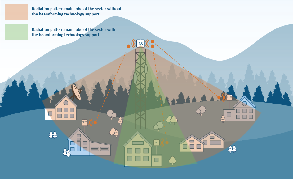
- Увеличение энергетики канала связи. На рисунке 1 представлено сравнение диаграммы направленности антенн с поддержкой beamforming и без неё. Следует учитывать, что мощность излучения устройства не изменилась, а за счёт того, что подведённая к антенне энергия излучается только в направлении конкретного абонента, уровень принимаемого абонентом сигнала существенно увеличивается. Аналогичный эффект наблюдается и в восходящем канале. Можно выделить следующие сценарии, использующие данное преимущество:
- Рост производительности (за счёт увеличения отношения сигнал/шум для абонентов, выполняющих передачу данных не на максимальном битрейте, становится возможным использование высших модуляционно-кодовых схем, определяющих пропускную способность канала связи).
- Увеличение срока службы устройств (рост энергетики канала связи, при условии, что необходимая производительность уже получена, может быть использован для снижения мощности излучения сигнала, что повысит срок службы радиопередатчика устройства).
- Увеличения дальности покрытия сектора (рост энергетики канала позволяет выполнять подключение новых абонентских устройств на большем расстоянии от сектора).
| Center |
|---|
Рисунок 1 - Сравнение диаграммы направленности сектора с поддержкой технологии формирования луча и её отсутствием |

...
An example of sector with beamforming |
The beamforming technology advantages
The advantages of using devices with the beamforming technology support:
- The link energy increasement. Figure 1 shows a comparison of the antenna's radiation pattern with and without beamforming support. Note that the radiation power of the device has not changed, and due to the fact that the energy supplied to the antenna is radiated only in the direction of a particular subscriber, the received signal level at the subscriber device increases significantly. A similar effect appears in the uplink as well. This advantage leads to the following benefits:
- Improved performance (subscribers performing data transmission not on the maximum bitrate, it can use higher modulation-code schemes to increase the bandwidth of the link, due to an increase in the signal-to-noise ratio).
- Longer device lifetime (due to the link energy increase, the radiation power can be reduced without affecting the performance, leading to the increasement of the device's radio transmitter lifetime).
- Sector coverage range increasement (higher link energy allows connection of new subscriber devices located at greater distances from the sector).
| Center |
|---|
Figure 1 - Radiation pattern of the sector with the beamforming technology support and without it |
- Improved directional properties of the antenna. Allows to increase security by reducing the risks of all sector's subscribers data interception. In case of beamforming technology support, the data transmission is performed only in the subscriber direction, therefore if an attacker performs similar actions, he will be able to access only the data of one subscriber.
- The ability to select the radiation direction automatically, reduces the requirements for the alignment and allows to determine the azimuth of the subscriber location, which can be useful in some scenarios (ex. with mobile objects).
- Using the BS sector with beamforming antenna reduces the local interference influence. Video 4 shows the interference effect in case of beamforming antenna usage. The noise falls into the side lobe of the radiation pattern, when the second and third subscribers are servicing, and does not have a significant effect on the useful signal. Since the data transmission direction to the first subscriber and the interference source coincide, the use of beamforming technology does not allow to reduce the local interference influence for this device. Although the beamforming technology support does not allow to completely neutralize the influence of interferences, its use can significantly improve the performance and reliability of the communication in some scenarios.
| Center | ||||||||
|---|---|---|---|---|---|---|---|---|
Видеоролик 4 - Пример влияния локальной помехи на сектор системы с технологией формирования луча |
Реализация
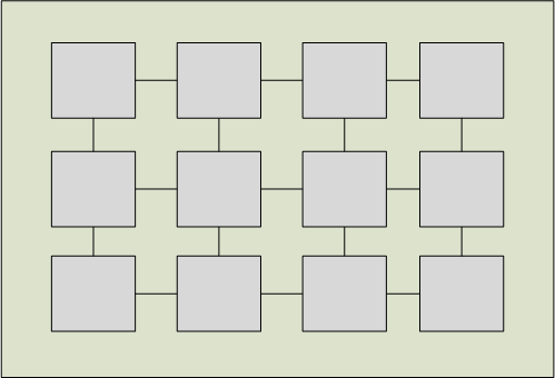
Современные устройства включают в себя несколько излучателей. Одной из конструкций, используемой в современной радиосвязи, является фазированная антенная решётка (см. рисунок 2), представляющая из себя матрицу проводящих элементов. Их форма и взаимное расположение определяют частотную избирательность и направленные свойства антенны.
...
Video 4 - An example of the local interference effect on sector with beamforming technology |
Implementation
Modern devices have several emitters. One of the structures used in modern radio communications is the phased antenna array (see Figure 2), which is a matrix of conducting elements. Their shape and relative position determine the frequency range and directional properties of the antenna.
A copy of the modulated signal from the radio module is supplied to each antenna element. In addition to the antenna array design, the radiation pattern is determined by the signal's characteristics from each of the radiating elements: by default, the signals are in-phase, but by intentionally introducing a phase delay, the shape and direction of the main lobe can be changed.
| Center |
|---|
Рисунок Figure 2 - Пример макета фазированной антенной решётки |
Описанный выше эффект используется в устройствах с технологией формирования луча. Подход к управлению диаграммой направленности делит такие устройства на две большие группы:
- Устройства с набором шаблонов диаграммы направленности (в память устройства вносят несколько шаблонов диаграммы направленности, которые, как правило, отличаются азимутом основного лепестка. Взаимодействие с конкретным абонентским устройством подразумевает использование одного из шаблонов, который лучше всего подходит по заданному критерию. Недостатком подхода является то, что конечный набор шаблонов не всегда позволяет выбрать максимально эффективную диаграмму направленности для клиентского устройства).
- Устройства без шаблонов диаграммы направленности (в соответствии с принимаемым от клиентского устройства сигнала, устройство формирует индивидуальную диаграмму направленности, руководствуясь одним из заложенных алгоритмов. Недостатком подхода являются высокие требования к вычислительным ресурсам).
Реализация в устройствах Инфинет
В продуктовом портфеле компании Инфинет технология формирования луча реализована в моделях секторов базовых станций R5000-Qmxb, входящих в семейство систем "точка-многоточка" InfiMAN 2x2.
Интегрированная антенна устройства R5000-Qmxb включают в себя 15 встроенных шаблонов диаграмм направленности с шириной главного лепестка 20º (коэффициент усиления 21 dBi), расположенных со смещением 5º друг от друга и один шаблон с шириной лепестка 90º (коэффициент усиления 15 dBi). В зависимости от выбранного шаблона диаграммы направленности устройство может работать в двух режимах:
- Широковещательный режим - использование диаграммы направленности с шириной главного лепестка 90º. Данный режим используется при обмене служебной информацией, когда за абонентским устройством ещё не закреплён один из узконаправленных шаблонов или необходимо актуализировать данные о выбранном шаблоне.
- Направленный режим - использование одного из 15 шаблонов диаграммы направленности с шириной главного лепестка 20º. Данный режим используется при непосредственной передаче данных.
...
An example of a phased array antenna layout |
The effect described above is used in devices with beamforming technology. The approach on how the radiation pattern control is performed, divides such devices into two large groups:
- Devices with a set of radiation pattern templates (devices have several radiation pattern templates in the memory that usually modify the azimuth of the main lobe. The interaction with a specific subscriber device implies using one of the templates, which is best suited for a given location. The disadvantage of this approach is that the final set of patterns does not always allow to choose the most efficient radiation pattern for the subscriber device).
- Devices without radiation pattern templates (in accordance to the signal received from the subscriber, the device generates an individual radiation pattern, using one of the embedded algorithms. The disadvantage of this approach is the high computing resources requirements).
Implementation in the InfiNet devices
In the InfiNet company's product portfolio, the beamforming technology is implemented in the R5000-Qmxb base station sector models of the InfiMAN 2x2 point-to-multipoint family and E5-BSQ base station sector models of the InfiMAN Evolution family.
R5000-Qmxb and E5-BSQ devices integrated antennas includes 15 built-in templates of the radiation pattern with a main lobe width of 20º (gain 21 dBi) located with an offset of 5º from each other and one template with a lobe width of 90º (gain 15 dBi). Depending on the chosen template, the device can operate in two modes:
- Broadcast mode - using the radiation pattern with a main lobe width of 90º. This mode is used to exchange service information, when the narrow, focused templates are not yet assigned or when it is necessary to update the data on the selected template.
- Directional mode — using one of the 15 radiation pattern templates with a main lobe width of 20º. This mode is used for direct data transfer.
Video 5 demonstrates the establishing of correspondence between the subscriber station and the radiation pattern template. The base station sector broadcasts requests addressed to all subscribers, using every narrow directional templates in turn. The request contains information about the template number. The subscriber estimates the level of each received signal, selects the maximum and sends the template number to the sector. After receiving information from the subscriber, the sector fills in the correspondence table and uses a template from the generated table , to interact with a specific client device. During operation the sector initiates the update of the correspondence table, adapting to possible changes in the external environment.
| Center | ||||||||
|---|---|---|---|---|---|---|---|---|
Видеоролик Video 5 - Механизм выбора шаблона диаграммы направленности для абонентского устройства |
Переход на систему с поддержкой технологии формирования луча не является трудозатратным - достаточно выполнить замену сектора базовой станции, причём может быть использована конфигурация прежнего устройства, т.к. они совместимы между собой, а технология формирования луча не требует настройки и выполняется прозрачно для пользователей и администраторов сети. Замену абонентских устройств производить не нужно - устройства совместимы между собой. Однако, есть два ограничения, которые требуется учитывать:
...
Template selection mechanism for subscriber device |
The migration to a system with beamforming technology support is not laborious - it is enough to perform the base station sector replacement, the configuration of the previous device is compatible with new sector, the beamforming technology does not need any additional settings and is performed transparently for users and network administrators. There is no need to replace subscriber devices - the devices are compatible with each other. However, there are two limitations to deal with:
...
- The power consumption of the devices with beamforming technology support is higher than for devices without it, therefore, IDU-BS-G (60W) (входят в комплект поставки).
- Устройства R5000-Qmxb могут быть использованы только с версией программного обеспечения с поддержкой технологии TDMA (характеристики двух типов ПО представлены в статье TDMA и Polling: особенности применения в беспроводных сетях). Замена программного обеспечения с поддержкой технологии Polling на программное обеспечение с поддержкой TDMA может быть выполнена в соответствии с инструкцией. При близком расположении нескольких секторов, например реализация схемы ABAB, рекомендуется использовать устройство синхронизации AUX-ODU-SYNC.
Дополнительные сценарии применения технологии формирования луча
Рассмотренные достоинства технологии формирования луча могут быть использованы в мобильных беспроводных системах связи. Подвижный характер абонентской или базовой станции оказывает сильное влияние на параметры канала связи, которые могут быть нивелированы с помощью использования устройств с технологией формирования луча. При использовании подобных устройств диаграмма направленности будет адаптироваться к изменениям внешней среды, пытаясь сохранить радиопараметры канала связи на максимальном уровне.
Следует иметь в виду, что реализация подобных проектов является нетривиальной задачей, требующей нестандартного подхода и смекалки. Одним из вариантов решения может быть использование устройств с технологией формирования луча на клиентской стороне, либо как на стороне абонента, так и на стороне базовой станции.
Дополнительные материалы
...
- power supplies are used to power the R5000-Qmxb and E5-BSQ devices.
- R5000-Qmxb and E5-BSQ devices can only use a software version with TDMA technology (the differences between the two types of software are described in the TDMA and Polling: Application features article). Software with Polling technology support can be upgraded to software with TDMA technology support according to the instruction. In case of adjacent sectors, for example, in the implementation of the ABAB scheme, it is recommended to use the AUX-ODU-SYNC synchronization device.
Additional application scenarios for beamforming technology
The above described beamforming technology advantages can be used in mobile wireless communication systems. The mobility of the subscriber or of the base station has a strong influence on the link parameters, which can be neutralized by using devices with beamforming technology. The radiation pattern of such devices will adapt to changes in the external environment, trying to keep the link radio parameters at the maximum level.
Note that the implementation of such projects is a complex task that requires an unconventional approach and ingenuity. A possible solution is to use devices with beamforming technology on the client side, or both on the subscriber side and on the base station side.
Additional documents
- Wireless Networking Fundamentals
- Qmxb versatility: Point-to-Multipoint and Point-to-Point with beamforming
- Success story: InfiNet solutions in FLEX network
- Beamforming Sectorial Antenna
- Datasheet Qmxb/5.300.2x300.2x21
- Документ "Электропитание беспроводных устройств «Инфинет»" в разделе "Документы" академии ИнфинетDatasheet E5-BSQ