| Center |
|---|
| Scroll Title |
|---|
|  Image Removed Image Removed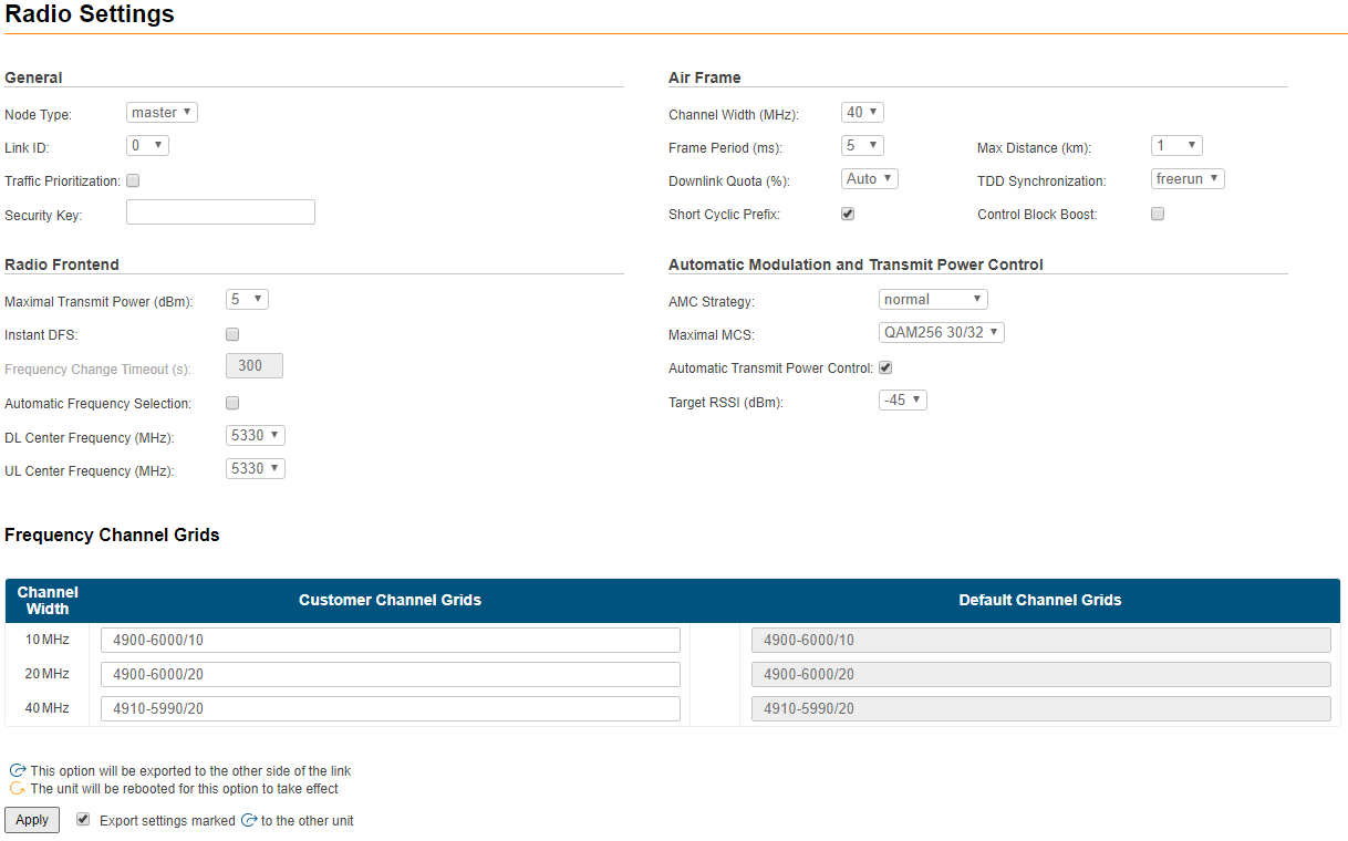 Image Added Image Added
|
|
The radio page is divided in two sections:
- "Radio settingsSettings" - allows you to configure general configure general radio parameters and features:
- General
- Air Frame
- Radio Frontend
- AMC
- Air FrameAutomatic Modulation and Transmit Power Control
- "Frequency Channel Grids" - specifies the the default and custom custom frequency domains for each bandwidth (10, 20, 40 MHz).
Radio
...
Settings
The following radio parameters can be configured under the "Radio
...
Settings" section:
| Center |
|---|
| Scroll Title |
|---|
| title | Table - Radio settings |
|---|
| | Radio parameter | Description |
|---|
| General |
|---|
| Node Type | - Set the node type to Master or Slave
- In the point-to-point link, one unit must be set to Master and the other one to Slave
|
| Traffic Prioritization | - Enable/disable prioritization strategy:
| | Link ID | - Use this parameter to avoid connecting a unit to a wrong peer if there are several co-located units using the same center frequency
- Specify different ID values for different link. Both ends of the same link must have the same ID. The value range is 0…15 in increments of 1
|
Center Frequency, MHz | Allows you to configure the Master/Slave center frequency in MHz | | Traffic Prioritization | - Enable/disable prioritization strategy. Unit will recognize the 802.1p tags in Ethernet frame headers. Based on these tags priorities will be autlomatically assigned to the frames when they are sent over the radio interface. After transmission over radio interface frames with tags are sent to Ethernet. Priorities may be adjusted manually (Configuring per-VLAN 802.1p priority).
| Note |
|---|
| If "VLAN-based Switching" is enabled and prioritization is configured for "Default VLAN", tags priorities will be autlomatically assigned to the frames when they are sent over the radio interface. In this case port modes must differ from "Untagged" and "Off". |
| | Security Key | - Set the secret key word for encoding of the protocol messages
- It must be up to 64 characters long, without spaces
- It must be the same at both ends of the link
| | Air Frame |
|---|
| Channel Width (MHz) | - Allows you to configure the channel width (in MHz). The possible values are: 10, 20 or 40 MHz
| | Frame period (ms) | - Allows you to set the air frame period duration (in ms). The value range is 2, 4, 5 or 10 ms
- A shorter frame period gives lower latency, but also has higher overheads
- Using longer frame periods cuts down overheads, but increases the latency
| Downlink Quota (%) | - Actual downlink/uplink ratio values through specifying the downlink subframe period relative to the whole frame
- Downlink Quota available values depend from:
- Channel width
- Short Cyclic prefix
- Frame period
- Max Distance
| | Short Cyclic Prefix | - Enable/disable short cyclic prefix option
- Cyclic prefix is used to mitigate inter-symbol interference due to multipath propagation environment
- Cyclic prefix size is always 1/8 for 10 MHz channel width
|
Transmit Power dBm configure the transmit power level - specify the maximum link distance (in
|
dBm value range is 0…27 dBm in increments of 1 dBm- possible values: from 1 to 100 in increments of 1 km
- The specified value must not be lower than the actual link distance, but it is recommended keep it as close as possible to the actual distance to avoid unnecessary overheads
- The recommended strategy is to set this parameter well above the actual distance after the units have been deployed based on the measured distance value taken from “xginfo stat” output
| | TDD Synchronization | - Allows you to configure the TDD synchronization source:
- “freerun” - the "slave" unit synchronization is performed with the built-in GPS/GLONASS receiver of the "master" unit
- “gnss” - synchronization from built-in GPS/GLONASS receiver
| Note |
|---|
| To ensure two Masters synchronization from the synchronization source: - The first Master must be set to "freerun" mode.
The second Master must be set to "1588" mode.
|
| | Control Block Boost | - Enable/disable control block boost option
- Control Block Boost improves link availability in the most difficult propagation and interference conditions due to the radio frame with control information transfer at duplicate transmit power
|
Maximal MCS | | Radio Frontend |
|---|
Downlink Center Frequency, MHz (5 GHz units) | - Allows you to configure the frequency in MHz at which data will be transmitted
- The frequency selection is automatically blocked when "Instant DFS" and "Automatic frequency selection" options are enabled
| Uplink Center Frequency, MHz (5 GHz units) | - Allows you to configure the
|
maximum MCS that can be used:QPSK 1/2QPSK 3/4QAM16 1/2QAM16 3/4QAM64 4/6QAM64 5/6QAM256 6/8QAM256 7/8QAM256 30/32QAM1024 8/10- frequency in MHz at which data will be received
- The frequency selection is automatically blocked when "Instant DFS" and "Automatic frequency selection" options are enabled
| Center Frequency, MHz (6 GHz units) | - Allows you to configure the center frequency
| | Maximal Transmit Power (dBm) | - Allows you to configure the transmit power level (in dBm). The value range is 0…27 dBm in increments of 1 dBm
| | Instant DFS | - Enable/disable Instant DFS option
| Note |
|---|
| The "Instant DFS" option is only available for the InfiLINK XG family 5 GHz devices. |
| | Automatic Frequency Change Timeout (s) | - Not available in case of Instant DFS option disabled
| | Automatic Frequency Selection | - Selects the frequency when link is establishing, unlike the "Instant DFS" option, which scans the medium when data are already transmitted through the link
- Is chozen automatically when the "Instant DFS" option is enabled. If the initial frequency selection is not required (link is already established), disable this function in order to prevent the radio disconnection.
| Note |
|---|
| The "Automatic Frequency Selection" option is NOT available for the InfiLINK XG 1000 family devices. |
| | Automatic Modulation and Transmit Power Control |
|---|
| AMC Strategy | - Allows you to select the AMC algorithm strategy:
|
“conservative” - “conservative” assumes using higher CINR thresholds in order to minimize the error rate
|
“aggressive” - “aggressive” lowers the thresholds in order to use higher modulation levels and thus increase the throughput
|
“normal” - “normal” represents a balance between the error rate and throughput values
|
TDD Synchronization| Maximal MCS | - Allows you to configure the
|
TDD synchronization source:- “freerun” unsynchronized frame start
- “gnss” synchronization from built-in GPS/GLONASS receiver
| Frame period (ms) | - Allows you to set the air frame period duration (in ms). The value range is 2, 4, 5 or 10 ms
- A shorter frame period gives lower latency, but also has higher overheads
- Using longer frame periods cuts down overheads, but increases the latency
| Downlink Quota (%) | - Actual downlink/uplink ratio values through specifying the downlink subframe period relative to the whole frame
- Downlink Quota available values depend from:
- Channel width
- Short Cyclic prefix
- Frame period
- Max Distance
| Max Distance (km) | Allows you to specify the maximum link distance (in kilometers). The possible values: from 1 to 100 in increments of 1 kmThe specified value must not be lower than the actual link distance, but it is recommended keep it as close as possible to the actual distance to avoid unnecessary overheadsThe recommended strategy is to set this parameter well above the actual distance after the units have been deployed based on the measured distance value taken from “xginfo stat” output- maximum MCS that can be used:
- QPSK 1/2
- QPSK 3/4
- QAM16 1/2
- QAM16 3/4
- QAM64 4/6
- QAM64 5/6
- QAM256 6/8
- QAM256 7/8
- QAM256 30/32
- QAM1024 8/10
| | Automatic Transmit Power Control | - ATPC Master
- The master unit manages the transmit power of the remote unit in order to achieve the target RSSI value of its own receiver
- ATPC Slave
- The slave unit corrects the transmit power of its own transmitter according to the master unit directions
- In general "ATPC Master" and "ATPC Slave" are not related to the "master" and "slave" parameters. The same unit can be as "ATPC Master" and "ATPC Slave"
| | Target RSSI (dBm) | The RSSI target value:- The RSSI value of the master tries to engage the target range, the center value of which is the "Target RSSI"
- Practical range: from -20 to -70 dBm (the actual: from -40 to -70 dBm)
|
|
|
| Note |
|---|
|
For the InfiLINK XG 1000 family models the following parameters can be configured for both radio modules: - DL Center Frequency
- UL Center Frequency.
The minimum required guard interval between center frequencies of "Carrier 0" (the first radio module) and "Carrier 1" (the second radio module) should be: - 20 MHz - for 10 MHz channel width
- 40 MHz - for 20 MHz channel width
- 80 MHz - for 40 MHz channel width.
| Center |
|---|
| Scroll Title |
|---|
| title | Figure - InfiLINK XG 1000 Radio Settings section |
|---|
| 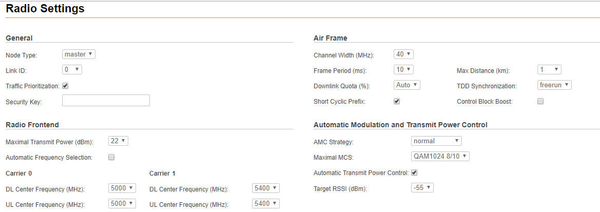 Image Added Image Added
|
|
|
| Warning |
|---|
|
Setting the source of synchronization takes effect only for the Master unit. |
| Warning |
|---|
|
Make Make sure that the built-in GNSS receiver is set up before enabling the “gnss” option (use “gps” command to check the status - it is recommended to use values of “HDOP” parameter up to 1.5 for reliable global timing synchronization). |
| Warning |
|---|
|
Please note that the following settings must be equal for the co-located units"master" and "slave" unit to establish the radio link: - Center Frequency
- Channel WidthMax Distance
- Frame Period
- Downlink Quota
- Short Cyclic Prefix
- Link ID
All co-located units must be Master units |
| Note |
|---|
|
In order to export and apply option marked Image Addedto the other side of the link check the box "Export settings marked Image Addedto the other side of the link check the box "Export settings marked Image Addedto the other unit" and click the "Apply" button. Image Addedto the other unit" and click the "Apply" button. |
| Note |
|---|
|
Safety apply settings mode is activated by default on devices. Mode principle of work is detailed described in the document "Safety apply settings in InfiLINK XG / InfiLINK XG 1000". |
Frequency Channel Grid
The licensed frequencies range per each bandwidth is displayed in the “Default Channel Grids” fields:
...
| Center |
|---|
| Scroll Title |
|---|
| title | Figure - Default Channel Grids |
|---|
|  Image Removed Image Removed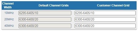 Image Added Image Added
|
|
Changes to these default values can be performed in the “"Customer Channel Grid” " fields, where you can:
- Limit the licensed frequencies range per each bandwidth
...
| Center |
|---|
| Scroll Title |
|---|
| title | Figure - Customer Channel Grid |
|---|
|  Image Removed Image Removed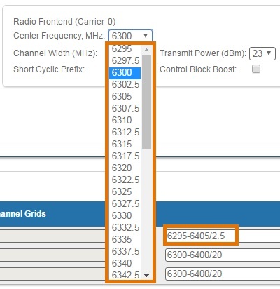 Image Added Image Added
|
|
The step must be >= 1 MHz and the frequencies range (determined by the license) cannot be exceeded.