| Gliffy Diagram |
|---|
| name | Совместимость режимов |
|---|
| pagePin | 1 |
|---|
|
...
| Center |
|---|
| Scroll Title |
|---|
| title-alignment | center |
|---|
| title | Figure - Configuration options |
|---|
| 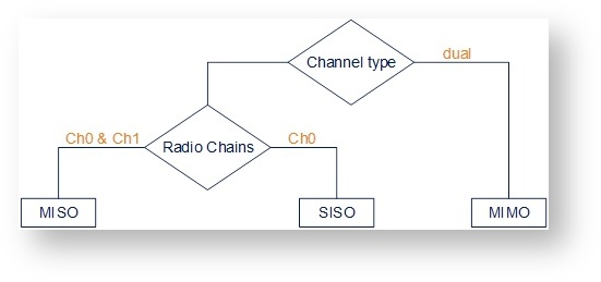 Image Removed Image Removed |
|
note | titleMIMO, MISO and SISO are | NOTE | |
If the "Single" mode is selected when, then "Chain #1" column (horizontal polarization) can be disabled for transmission (TX) and / or reception (RX):
| Center |
|---|
| Scroll Title |
|---|
| title-alignment | center |
|---|
| title | Figure - Chain # |
|---|
|  Image Added Image Added
|
|
| Note |
|---|
|
MIMO, MISO and SISO are defined from the perspective of the data sent by the local unit (not considering the number of physical antennas used for tx and rx like in the classical definition). Therefore, these represent local configuration options. For example, one stream of data can be sent by one chain (1 antenna) corresponding to SISO or the same stream can be sent by both chains (2 antennas) corresponding to MISO. |
...
Different data streams are transmitted over "Chain #0" and "Chain #1". MIMO uses multiple antennas at both the transmitter and receiver side to improve communication performance and data is sent on both the horizontal and vertical polarizations (data is space-time coded - spatial multiplexing, to improve the reliability of data transmission):
| Center |
|---|
| Scroll Title |
|---|
| title-alignment | center |
|---|
| title | Table - Settings for MIMO mode |
|---|
| | Channel Type | Dual |
|---|
| Radio Chain | #0 | #1 |
|---|
| Rx | | Background Color |
|---|
Activated |
| | Background Color |
|---|
Activated |
|
|---|
| Tx | | Background Color |
|---|
Activated |
| | Background Color |
|---|
Activated |
|
|---|
|
|
...
The same data streams are transmitted over "Chain #0" and "Chain #1", lowering the performance of the link, but enhancing the ability to transmit data in case of interference or obstacles in transmission path (a special mode of operation of MIMO devices used in NLOS conditions or in a noisy RF environment):
| Center |
|---|
| scroll-title |
|---|
| title-alignment | center |
|---|
| title | Table - Settings for MISO mode |
|---|
| | Channel Type | Single |
|---|
| Radio Chain | #0 | #1 |
|---|
| Rx | | Background Color |
|---|
Activated |
| | Background Color |
|---|
Activated |
|
|---|
| Tx | | Background Color |
|---|
Activated |
| | Background Color |
|---|
Activated |
|
|---|
|
|
...
The data streams are transmitted over Chain #0 (corresponding to vertical polarization) only, lowering the performance of the link, but increasing the link distance (transmitter operates with one antenna as does the receiver; there is no diversity and no additional processing for recomposing the Rx signal):
| Center |
|---|
| Scroll Title |
|---|
| title-alignment | center |
|---|
| title | Table - Settings for SISO mode |
|---|
| | Channel Type | Single |
|---|
| Radio Chain | #0 | #1 |
|---|
| Rx | | Background Color |
|---|
Activated |
| | Background Color |
|---|
| Deactivated |
|
|---|
| Tx | | Background Color |
|---|
Activated |
| | Background Color |
|---|
| Deactivated |
|
|---|
|
|
The picture below summarizes the link establishment between two units that are configured in different operational modes. As it can be noticed, only the combination MIMO – SISO is not functional.
| Center |
|---|
| Scroll Title |
|---|
| title-alignment | center |
|---|
| title | Figure - Radio link establishment |
|---|
| 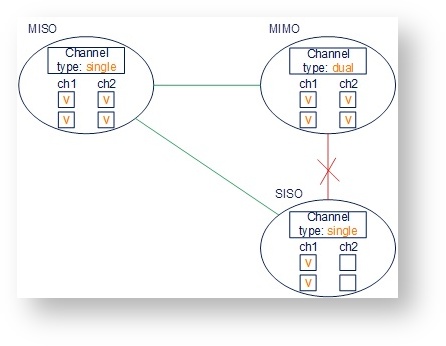 Image Removed Image Removed | | Gliffy Diagram |
|---|
| name | Совместимость режимов |
|---|
| pagePin | 1 |
|---|
|
|
|
"prf" subsection
In the "prf" subsection, you can configure the pseudo-RF link as a MINT network RF link as a MINT network node. The "prf" subsection is available for configurations only after at least one pseudo-RF interface RF interface has been created in "Network Settings" section. Pseudo-RF virtual RF virtual interface is used to provide MINTprovide MINT-over-Ethernet. Every BS or CPE supports PRF interfacesEvery BS or CPE supports PRF interfaces. All parameters available in "prf" subsection are explained in "rf5rf6.0" subsection above:
| Center |
|---|
| Scroll Title |
|---|
| title-alignment | center |
|---|
| title | Figure - PRF settings |
|---|
| 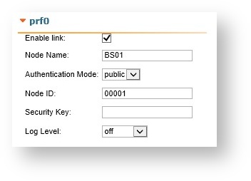 Image Removed Image Removed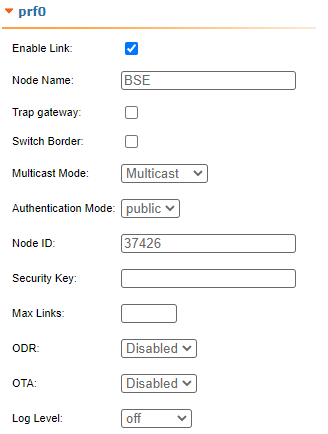 Image Added Image Added
|
|
"Join" subsection
...
In order to join the interfaces, simply enable the check boxes of the corresponding interfaces, as shown in the screenshot below:
| Center |
|---|
| scroll-title |
|---|
| title-alignment | center |
|---|
| title | Figure - «Remove» and «Add Join» buttons |
|---|
| 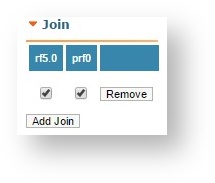 Image Removed Image Removed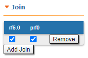 Image Added Image Added
|
|