NOTE
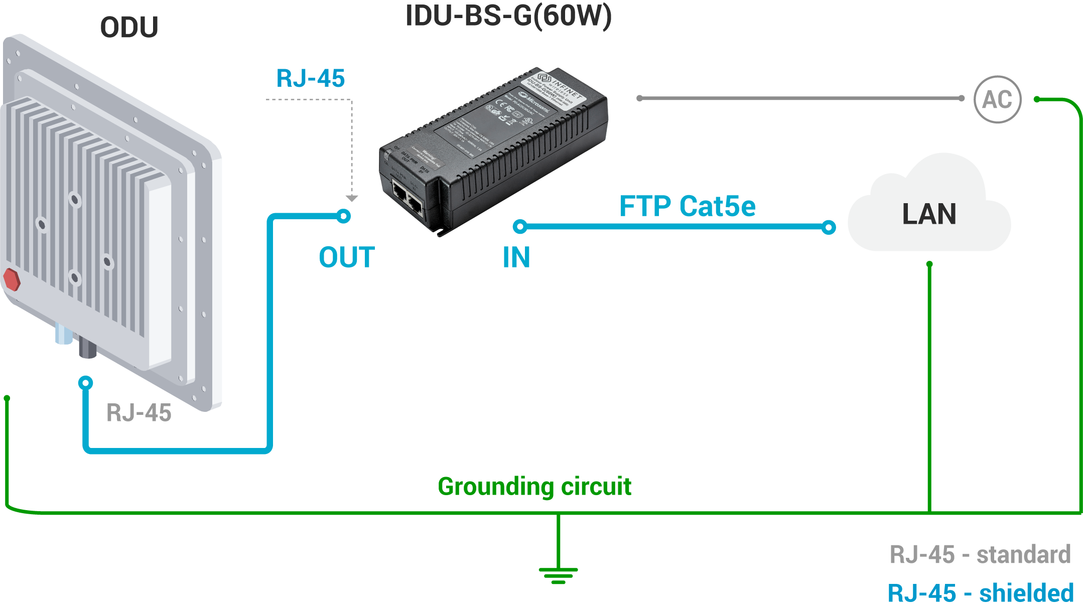
The end of the FTP service cable that is connected to IDU should be assembled with a shielded RJ-45 connector. The other end of the FTP service cable (connected to ODU) should be assembled with unshielded RJ-45 connector.
IDU is grounded via a three-conductor power cord and a grounded socket. The data & power wires pickups are terminated via IDU protection scheme (three-conductor power cord and a grounded socket).
NOTE
Antenna pole, tower, ODU and lightning arrestor should be connected to the common ground ring. Grounding cables should be no less than 10AWG thick and must use corrosion-resistant connectors. At the end of the FTP cable that connects to the IDU should be used an RJ-45 connector with grounding. At the other end of the cable (connected to the ODU) should be used an RJ-45 connector without grounding.
Special attention should be paid if the antenna used is not DC-shorted. In this case, an additional lightning arrestor should be used between the antenna and ODU.
Grounding diagram is shown in the picture below.
Grounding when using AUX-ODU-INJ-G
AUX-ODU-INJ-G should be properly assembled, mounted and grounded.
AUX-ODU-INJ-G Mounting
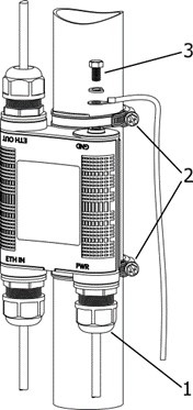
AUX-ODU-INJ-G can be can be installed on a pole, using hose clamps (2). Attach the grounding cable (min cross-section 2.5 mm2) to the case, using grounding bolt (3).
| Item | Name |
| 1 | Cable gland | |
| 2 | Clamps | |
| 3 | Grounding bolt |
CAUTION
Missing or bad grounding may leave the unit vulnerable to lightning damage.
AUX-ODU-INJ-G Cable Gland Assembly
In order to ensure that the cable gland remains sealed under any environmental conditions, please, follow the assembly sequence according to procedure below:
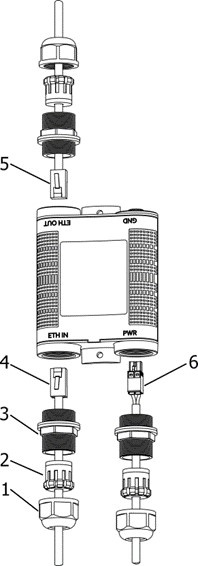
1) Put the cable gland nut (1), the split sealing grommet (2) and the cable gland threaded coupling (3) onto the cable FTP Cat5e
2) Crimp the connector onto the cable using the crimping tool:
CAUTION
Make sure that the connector is well crimped. A loose connector can damage the device. Please note that such damage is not coveded by the warranty.
- For connection to "ETH IN" terminate the cable with the unshielded RJ-45 connector (4) according to the EIA/TIA-568B
- For connection to "ETH OUT" terminate the cable with the shielded RJ45 connector (5) according to the EIA/TIA-568B (to provide grounding circuit)
- For connection to "PWR" terminate a cable with the power connector (6).
NOTE
Allowed to use a pre-crimped cable with RJ-45 connectors.
3) Insert the connector of the pre-terminated cable into the corresponding socket until you hear a click.
4) Screw the cable gland threaded coupling (3) into the port and tighten it. Do not apply excessive force.
5) Tighten the sealing grommet (2) by the cable gland nut (1). Do not apply excessive force.
| Item | Name |
| 1 | Cable gland nut | |
| 2 | Sealing grommet | |
| 3 | Cable gland threaded coupling | |
| 4 | Unshielded RJ-45 connector | |
| 5 | Shielded RJ-45 connector | |
| 6 | Power connector |
Power connector scheme is below
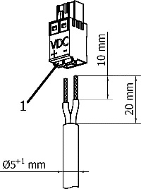
Follow requirements:
- Press on these catchers (1) when the cable is terminated;
- Use the round cable with diameter from 5mm to 6mm with conductor cross-section from 0.5mm to 2.5mm;
- FTP Cat5e cable may be used.
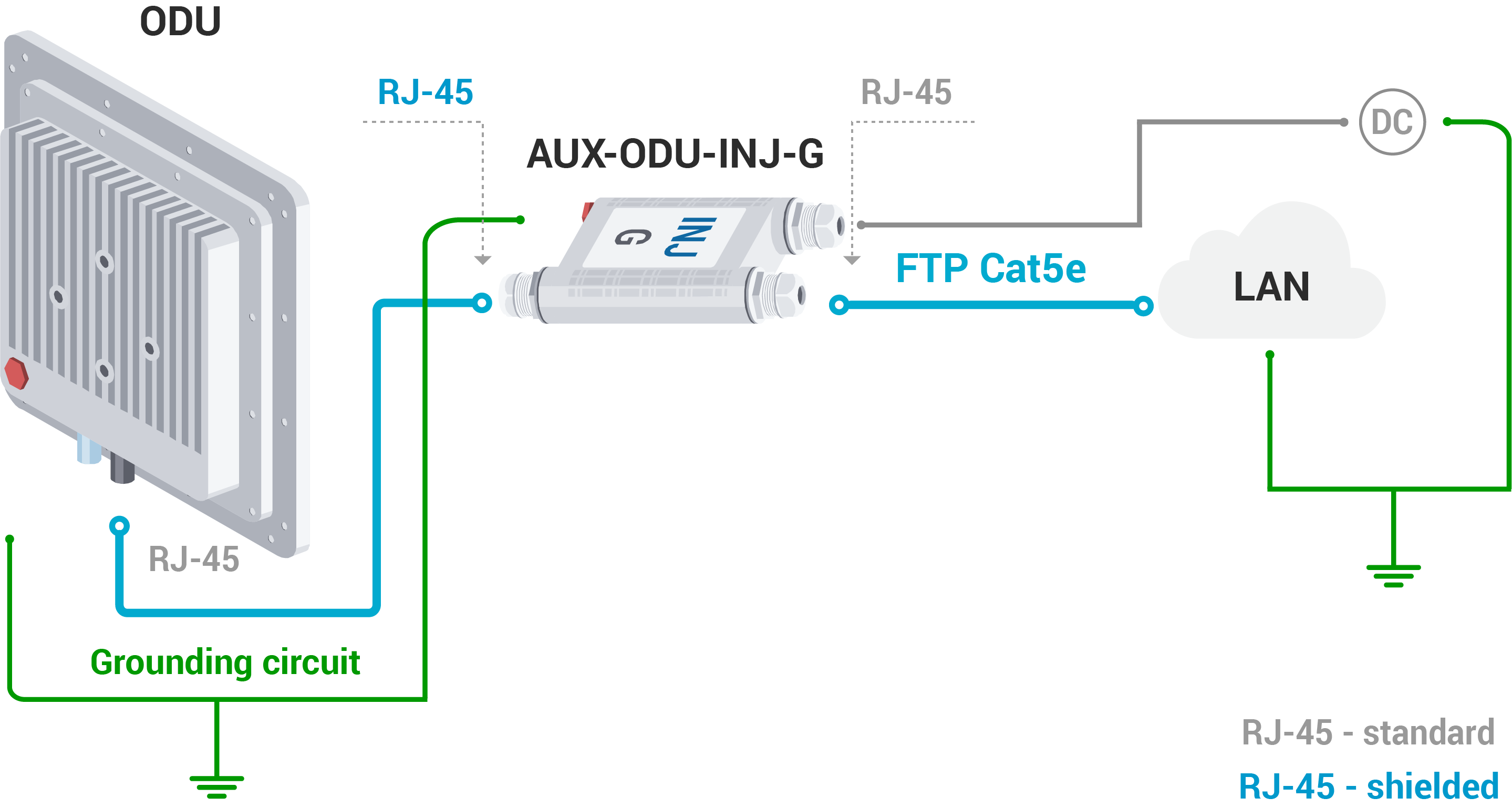
AUX-ODU-INJ-G Grounding Scheme
The grounding and lightning protection initial procedures when using AUX-ODU-INJ-G are similar to those when using regular IDU.
Grounding when using AUX-ODU-LPU-G
Grounding when using AUX-ODU-SYNC
AUX-ODU-SYNC Mounting
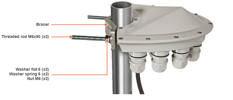
AUX-ODU-SYNC can be installed on a pole, using fasteners from the delivery package:
- Screw the threaded rod to the unit case.
- Tighten the device and the bracer on the pole and fix them by the threaded rod using the nuts and washers as shown at the picture
- Attach the grounding cable to the unit case using the grounding bolt.
CAUTION
Missing or bad grounding may leave the unit vulnerable to lightning damage.
AUX-ODU-SYNC Cable gland Assembling
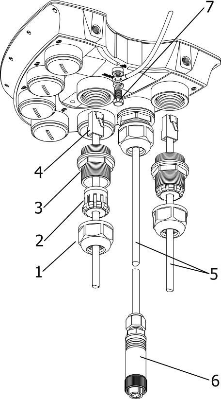
In order to ensure that the cable gland remains sealed under any environmental conditions, please, follow the assembly sequence according to the procedure below:
- Put the cable gland nut (1), the split sealing grommet (2) and the cable gland threaded coupling (3) onto the cable
Crimp the connector onto the cable using the crimping tool:
CAUTION
Make sure that the connector is well-crimped. A loose connector can damage the device. Please note that such damage is not covered by the warranty.
- For connection to the port Power terminate the FTP Cat.5e cable with the unshielded RJ-45 connector (4) according to the EIA/TIA-568B. Do not use the shielded RJ-45 connector on this end of the cable as it should be attached on the IDU end (to provide grounding circuit)
- For connection to the ports 0-6 use the ready-assembled specialized CAB-SYNC or CAB-SYNC-E (5) cables
- Insert the connector of the pre-terminated cable into the corresponding socket until you hear a click
- Screw the cable gland threaded coupling (3) into the port and tighten it. Do not apply excessive force
- Tighten the sealing grommet (2) by the cable gland nut (1). Do not apply excessive force.
CAUTION
Please note that the pressure equalization system in Infinet devices is performed via gas exchange through a cable gland and Ethernet cable jacket with a dry room where the power supply is installed. In order to avoid AUX-ODU-SYNC failure due to moisture entering the device, for example, during the pressure drop during the rain, the cable gland assembly requirements should be met and there are should be no cracks in the Ethernet cable jacket.
In addition, you should avoid the Ethernet cable bending near the AUX-ODU-SYNC and pinching with clamps, that can bring to the pressure equalization system fault between the internal volume of the sealed AUX-ODU-SYNC and the external environment during a sudden air temperature change. This may lead to the leakage and device failures.
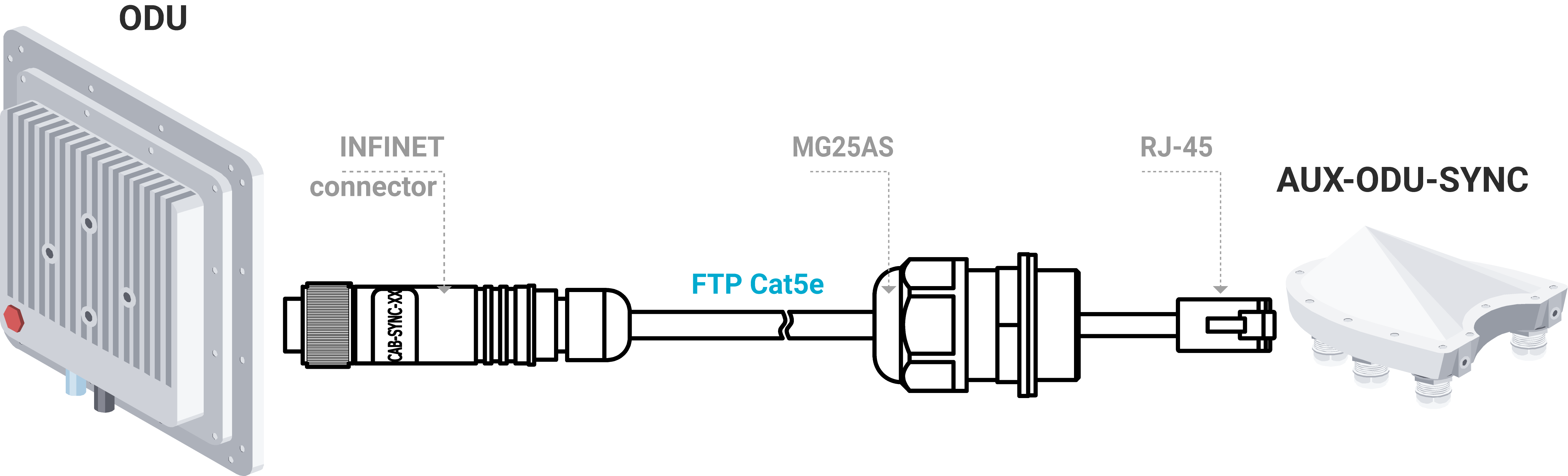
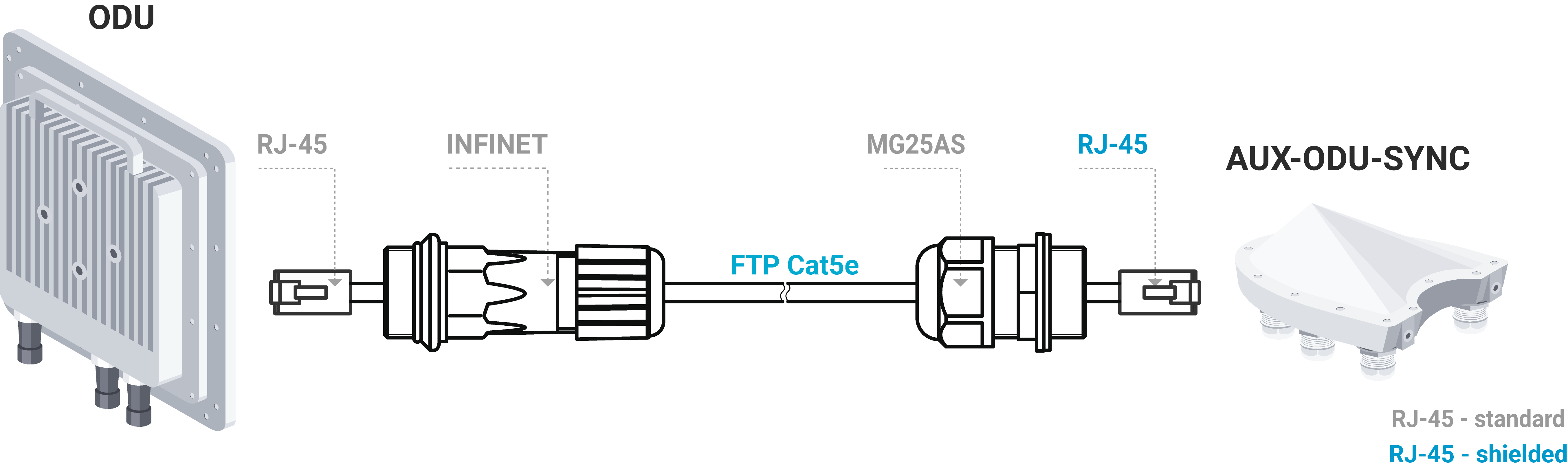
AUX-ODU-SYNC Connection to ODU
To connect AUX-ODU-SYNC to the units use the ready-assembled specialized CAB-SYNC cables for InfiMAN 2x2 and InfiLINK 2x2 PRO devices or CAB-SYNC-E cables for InfiMAN Evolution base station sectors. CAB-SYNC and CAB-SYNC-E must be ordered additionally. Information about CAB-SYNC and CAB-SYNC-E cables is available at Infinet web site in the "Accessories" section.
InfiMAN 2x2 and InfiLINK 2x2 PRO
To connect AUX-ODU-SYNC to ODU insert the INFINET connector of the CAB-SYNC cable to the console port of ODU and tighten the cap nut.
InfiMAN Evolution base station sector
To connect AUX-ODU-SYNC to ODU insert the RJ-45 connector with INFINET cable gland of the CAB-SYNC-E into the corresponding socket of the ODU until you hear a click. Perform the device port insulation with a cable gland as instructed above.
NOTE
Synchronization settings with AUX-ODU-SYNC is described in the document: