Table of content
Task description
Let's look at the example of an ODR configuration at the following scheme (Figure 1):
- wireless links are established between BS1, CPE2 and CPE3 devices, BS1 is configured as a Maser, CPE2, CPE3 - as Slaves;
- each wireless device is connected to a wired network segment, each segment uses its own IP addressing;
- router R1 is also connected to LAN-3, as well as to LAN-6, LAN-7, LAN-8 networks;
- it is necessary to organize connectivity between all networks by configuring the ODR protocol on the BS1, CPE2 and CPE3 wireless devices.
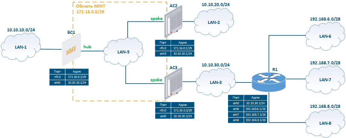
Figure 1 - The scheme to demonstrate ODR configuration example
Solution
Let's perform a step by step configuration of devices in accordance with the task. In addition to the ODR configuration, to establish communication with LAN-6, LAN-7, LAN-8 the static routing will be used (see Static routing).
The ODR configuration will be performed via CLI, after each step, routing information will be outputted for analysis.
Pre-configuration
| Description | Make pre-configuration of devices: establish wireless connection. |
|---|---|
BS1 | Set IP addresses ifc eth0 10.10.10.1/24 ifc rf5.0 172.16.0.1/29 Disable switching switch stop Establish radio link rf rf5.0 band 20 rf rf5.0 freq 5000 mint rf5.0 -name "BS_1" mint rf5.0 -type master |
| CPE2 | Set IP addresses ifc eth0 10.10.20.2/24 ifc rf5.0 172.16.0.2/29 Disable switching switch stop Establish radio link mint rf5.0 -name "CPE_2" mint rf5.0 -type slave mint rf5.0 prof 1 -band 20 -freq 5000 -type slave |
CPE3 | Set IP addresses ifc eth0 10.10.30.3/24 ifc rf5.0 172.16.0.3/29 Disable switching switch stop Establish radio link mint rf5.0 -name "CPE_3" mint rf5.0 -type slave mint rf5.0 prof 1 -band 20 -freq 5000 -type slave |
Description | Analyze the routing table on each device. There are two entries for directly attached networks associated with eth0 and rf5.0 interfaces. |
|---|---|
BS1 | BS_1#1> netstat -r Routing tables Destination Gateway Flags Refs Use Interface 10.10.10.0/24 link#2 UC 0 0 eth0 127.0.0.1 127.0.0.1 UH 1 473 lo0 172.16.0.0/29 link#3 UC 0 0 rf5.0 224.0.0.0/8 127.0.0.1 UGS 0 15780 lo0 |
CPE2 | AS_2#2> netstat -r Routing tables Destination Gateway Flags Refs Use Interface 10.10.20.0/24 link#2 UC 0 0 eth0 127.0.0.1 127.0.0.1 UH 1 432 lo0 172.16.0.0/29 link#3 UC 0 0 rf5.0 224.0.0.0/8 127.0.0.1 UGS 0 18457 lo0 |
CPE3 | AS_3#1> netstat -r Routing tables Destination Gateway Flags Refs Use Interface 10.10.30.0/24 link#2 UC 0 0 eth0 127.0.0.1 127.0.0.1 UH 1 560 lo0 172.16.0.0/29 link#3 UC 0 0 rf5.0 224.0.0.0/8 127.0.0.1 UGS 0 10686 lo0 |
ODR configuration
| Description | Enable the ODR protocol operation on wireless devices: assign the hub role to the BS1 device, to the CPE2, CPE3 devices - spoke. |
|---|---|
| BS1 | mint rf5.0 -odr hub |
| CPE2 | mint rf5.0 -odr spoke |
| CPE3 | mint rf5.0 -odr spoke |
| Description | Analyze information about ODR protocol operation:
|
|---|---|
| BS1 | BS_1#1> mint rf5.0 -odr show
rf5.0: ODR state - HUB
List of active Spokes:
00043513724E "AS_3"
10.10.30.3/24
000435109CC0 "AS_2"
10.10.20.2/24
Total Spokes: 2
|
| CPE2 | AS_2#2> mint rf5.0 -odr show rf5.0: ODR state - SPOKE Preffered HUB: 00043510E5B9 "BS_1" List of HUBs: 00043510E5B9 "BS_1", cost 51, hops 1 Exported routes: 10.10.20.2/24 |
| CPE3 | AS_3#1> mint rf5.0 -odr show rf5.0: ODR state - SPOKE Preffered HUB: 00043510E5B9 "BS_1" List of HUBs: 00043510E5B9 "BS_1", cost 51, hops 1 Exported routes: 10.10.30.3/24 |
| Description | Analyze the routing table of wireless devices:
|
|---|---|
| BS1 | BS_1#1> netstat -r Routing tables Destination Gateway Flags Refs Use Interface 10.10.10.0/24 link#2 UC 0 0 eth0 10.10.20.0/24 00:04:35:10:9c:c0 ULO 0 0 rf5.0 10.10.30.0/24 00:04:35:13:72:4e ULO 0 0 rf5.0 127.0.0.1 127.0.0.1 UH 1 473 lo0 172.16.0.0/29 link#3 UC 0 0 rf5.0 224.0.0.0/8 127.0.0.1 UGS 0 15780 lo |
| CPE2 | AS_2#2> netstat -r Routing tables Destination Gateway Flags Refs Use Interface mintGateway BS_1 rf5.0 10.10.20.0/24 link#2 UC 0 0 eth0 127.0.0.1 127.0.0.1 UH 1 432 lo0 172.16.0.0/29 link#3 UC 0 0 rf5.0 224.0.0.0/8 127.0.0.1 UGS 0 18457 lo0 |
| CPE3 | AS_3#1> netstat -r Routing tables Destination Gateway Flags Refs Use Interface mintGateway BS_1 rf5.0 10.10.30.0/24 link#2 UC 0 0 eth0 127.0.0.1 127.0.0.1 UH 1 560 lo0 172.16.0.0/29 link#3 UC 0 0 rf5.0 224.0.0.0/8 127.0.0.1 UGS 0 10686 lo |
Add static routes
The network segments LAN-6, LAN-7, LAN-8 are connected to the router R1, while the CPE3 does not have interfaces connected to these networks, so there is no routing information about these networks in the routing table. One way to fix this is to add static routes to the CPE3 and R1 routing table. Let's assume that the R1configuration has already been completed, so it is necessary to make changes to the CPE3 configuration.
| Description | Add static routes for LAN-6, LAN-7 and LAN-8 networks to the CPE3 routing table. |
|---|---|
| BS1 | Changes are not required. |
| CPE2 | Changes are not required. |
| CPE3 | route add 192.168.6.0/28 10.10.30.1 route add 192.168.7.0/28 10.10.30.1 route add 192.168.8.0/28 10.10.30.1 |
| Description | Changes in the devices routing tables:
|
|---|---|
| BS1 | BS_1#1> netstat -r Routing tables Destination Gateway Flags Refs Use Interface 10.10.10.0/24 link#2 UC 0 0 eth0 10.10.20.0/24 00:04:35:10:9c:c0 ULO 0 0 rf5.0 10.10.30.0/24 00:04:35:13:72:4e ULO 0 0 rf5.0 127.0.0.1 127.0.0.1 UH 1 473 lo0 172.16.0.0/29 link#3 UC 0 0 rf5.0 224.0.0.0/8 127.0.0.1 UGS 0 15780 lo |
| CPE2 | AS_2#2> netstat -r Routing tables Destination Gateway Flags Refs Use Interface mintGateway BS_1 rf5.0 10.10.20.0/24 link#2 UC 0 0 eth0 127.0.0.1 127.0.0.1 UH 1 432 lo0 172.16.0.0/29 link#3 UC 0 0 rf5.0 224.0.0.0/8 127.0.0.1 UGS 0 18457 lo0 |
| CPE3 | AS_3#1> netstat -r Routing tables Destination Gateway Flags Refs Use Interface mintGateway BS_1 rf5.0 10.10.30.0/24 link#2 UC 0 0 eth0 127.0.0.1 127.0.0.1 UH 1 560 lo0 172.16.0.0/29 link#3 UC 0 0 rf5.0 192.168.6.0/28 10.10.30.1 UGS 0 0 eth0 192.168.7.0/28 10.10.30.1 UGS 0 0 eth0 192.168.8.0/28 10.10.30.1 UGS 0 0 eth0 224.0.0.0/8 127.0.0.1 UGS 0 10686 lo0 |
Static routes export
In order to transmit routing information about LAN-6, LAN-7 and LAN-8 to all wireless devices, it is necessary to export static records to ODR. This operation can be performed using the CPE3 configuration, since the routing table of this device contains static entries and the rf5.0 interface supports the ODR.
| Description | Export static routes to ODR. |
|---|---|
| BS1 | Changes are not required. |
| CPE2 | Changes are not required. |
| CPE3 | mint rf5.0 -odr spoke kernel |
| Description | Analyze the ODR protocol operation at CPE3. Network paths to 192.168.6.0/28, 192.168.7.0/28 and 192.168.8.0/28 networks have been added to the list of exported routes. |
|---|---|
| BS1 | Changes are not required. |
| CPE2 | Changes are not required. |
| CPE3 | AS_3#1> mint rf5.0 -odr show rf5.0: ODR state - SPOKE Preffered HUB: 00043510E5B9 "BS_1" List of HUBs: 00043510E5B9 "BS_1", cost 51, hops 1 Exported routes: 10.10.30.3/24 192.168.6.0/28 192.168.7.0/28 192.168.8.0/28 |
| Description | Analyze changes in the devices routing tables:
|
|---|---|
| BS1 | BS_1#1> netstat -r Routing tables Destination Gateway Flags Refs Use Interface 10.10.10.0/24 link#2 UC 0 0 eth0 10.10.20.0/24 00:04:35:10:9c:c0 ULO 0 0 rf5.0 10.10.30.0/24 00:04:35:13:72:4e ULO 0 0 rf5.0 127.0.0.1 127.0.0.1 UH 1 473 lo0 172.16.0.0/29 link#3 UC 0 0 rf5.0 192.168.6.0/28 00:04:35:13:72:4e ULO 0 0 rf5.0 192.168.7.0/28 00:04:35:13:72:4e ULO 0 0 rf5.0 192.168.8.0/28 00:04:35:13:72:4e ULO 0 0 rf5.0 224.0.0.0/8 127.0.0.1 UGS 0 15780 lo |
| CPE2 | AS_2#2> netstat -r Routing tables Destination Gateway Flags Refs Use Interface mintGateway BS_1 rf5.0 10.10.20.0/24 link#2 UC 0 0 eth0 127.0.0.1 127.0.0.1 UH 1 432 lo0 172.16.0.0/29 link#3 UC 0 0 rf5.0 224.0.0.0/8 127.0.0.1 UGS 0 18457 lo |
| CPE3 | AS_3#1> netstat -r Routing tables Destination Gateway Flags Refs Use Interface mintGateway BS_1 rf5.0 10.10.30.0/24 link#2 UC 0 0 eth0 127.0.0.1 127.0.0.1 UH 1 560 lo0 172.16.0.0/29 link#3 UC 0 0 rf5.0 192.168.6.0/28 10.10.30.1 UGS 0 0 eth0 192.168.7.0/28 10.10.30.1 UGS 0 0 eth0 192.168.8.0/28 10.10.30.1 UGS 0 0 eth0 224.0.0.0/8 127.0.0.1 UGS 0 10686 lo |
ACL application
Filters can be applied to the routing information exported by spoke devices. Let's look at the examples of filtering exported information.
| Description | Configure the routing information filtering on the CPE3 to allow the device to export only a static route to the 192.168.6.0/28 network. |
|---|---|
| BS1 | Changes are not required. |
| CPE2 | Changes are not required. |
| CPE3 | acl add $ODR net 192.168.6.0/28 mint rf5.0 -odr spoke kernel $ODR |
| Description | Analyze the ODR protocol operation at CPE3. The entries about the 192.168.7.0/28 and 192.168.8.0/28 networks have been removed from the exported routes list due to the filter. The information about the 10.10.30.0/24 network is exported because the created filter was applied only to static routes (kernel), and the network 10.10.30.0/24 is directly connected. |
|---|---|
| BS1 | Changes are not required. |
| CPE2 | Changes are not required. |
| CPE3 | AS_3#1> mint rf5.0 -odr show rf5.0: ODR state - SPOKE Preffered HUB: 00043510E5B9 "BS_1" List of HUBs: 00043510E5B9 "BS_1", cost 51, hops 1 Exported routes: 10.10.30.3/24 192.168.6.0/28 |
| Description | Analyze changes in the devices routing tables:
|
|---|---|
| BS1 | BS_1#1> netstat -r Routing tables Destination Gateway Flags Refs Use Interface 10.10.10.0/24 link#2 UC 0 0 eth0 10.10.20.0/24 00:04:35:10:9c:c0 ULO 0 0 rf5.0 10.10.30.0/24 00:04:35:13:72:4e ULO 0 0 rf5.0 127.0.0.1 127.0.0.1 UH 1 473 lo0 172.16.0.0/29 link#3 UC 0 0 rf5.0 192.168.6.0/28 00:04:35:13:72:4e ULO 0 0 rf5.0 224.0.0.0/8 127.0.0.1 UGS 0 15780 lo |
| CPE2 | AS_2#2> netstat -r Routing tables Destination Gateway Flags Refs Use Interface mintGateway BS_1 rf5.0 10.10.20.0/24 link#2 UC 0 0 eth0 127.0.0.1 127.0.0.1 UH 1 432 lo0 172.16.0.0/29 link#3 UC 0 0 rf5.0 224.0.0.0/8 127.0.0.1 UGS 0 18457 lo |
| CPE3 | AS_3#1> netstat -r Routing tables Destination Gateway Flags Refs Use Interface mintGateway BS_1 rf5.0 10.10.30.0/24 link#2 UC 0 0 eth0 127.0.0.1 127.0.0.1 UH 1 560 lo0 172.16.0.0/29 link#3 UC 0 0 rf5.0 192.168.6.0/28 10.10.30.1 UGS 0 0 eth0 192.168.7.0/28 10.10.30.1 UGS 0 0 eth0 192.168.8.0/28 10.10.30.1 UGS 0 0 eth0 224.0.0.0/8 127.0.0.1 UGS 0 10686 lo |
| Description | Let's look at the opposite situation. Configure filtering of routing information on CPE3 to allow the device to export all static routes, except for the route to the 192.168.6.0/28 network. |
|---|---|
| BS1 | Changes are not required. |
| CPE2 | Changes are not required. |
| CPE3 | mint rf5.0 -odr spoke -kernel $ODR |
| Description | Analyze the ODR protocol operation at CPE3. The CPE3 exports static routes to the 192.168.7.0/28 and 192.168.8.0/28 networks and filters the route information about 192.168.6.0/28. |
|---|---|
| BS1 | Changes are not required. |
| CPE2 | Changes are not required. |
| CPE3 | AS_3#1> mint rf5.0 -odr show rf5.0: ODR state - SPOKE Preffered HUB: 00043510E5B9 "BS_1" List of HUBs: 00043510E5B9 "BS_1", cost 51, hops 1 Exported routes: 10.10.30.3/24 192.168.7.0/28 192.168.8.0/28 |
| Description | Analyze changes in the devices routing tables:
|
|---|---|
| BS1 | BS_1#1> netstat -r Routing tables Destination Gateway Flags Refs Use Interface 10.10.10.0/24 link#2 UC 0 0 eth0 10.10.20.0/24 00:04:35:10:9c:c0 ULO 0 0 rf5.0 10.10.30.0/24 00:04:35:13:72:4e ULO 0 0 rf5.0 127.0.0.1 127.0.0.1 UH 1 473 lo0 172.16.0.0/29 link#3 UC 0 0 rf5.0 192.168.7.0/28 00:04:35:13:72:4e ULO 0 0 rf5.0 192.168.8.0/28 00:04:35:13:72:4e ULO 0 0 rf5.0 224.0.0.0/8 127.0.0.1 UGS 0 15780 lo0 |
| CPE2 | AS_2#2> netstat -r Routing tables Destination Gateway Flags Refs Use Interface mintGateway BS_1 rf5.0 10.10.20.0/24 link#2 UC 0 0 eth0 127.0.0.1 127.0.0.1 UH 1 432 lo0 172.16.0.0/29 link#3 UC 0 0 rf5.0 224.0.0.0/8 127.0.0.1 UGS 0 18457 lo0 |
| CPE3 | AS_3#1> netstat -r Routing tables Destination Gateway Flags Refs Use Interface mintGateway BS_1 rf5.0 10.10.30.0/24 link#2 UC 0 0 eth0 127.0.0.1 127.0.0.1 UH 1 560 lo0 172.16.0.0/29 link#3 UC 0 0 rf5.0 192.168.6.0/28 10.10.30.1 UGS 0 0 eth0 192.168.7.0/28 10.10.30.1 UGS 0 0 eth0 192.168.8.0/28 10.10.30.1 UGS 0 0 eth0 224.0.0.0/8 127.0.0.1 UGS 0 10686 lo0 |