Table of content
ODR protocol
ODR (On Demand Routing) - the protocol for a routing information propagation used in a star network topology. The point-to-multipoint topology is a star, so ODR is widely used in wireless networks. The ODR algorithm unlike the other dynamic routing protocols, is very simple, so its operation is not resource-intensive.
Let's look at the ODR protocol operation on the example (Figure 1). The network scheme consists of a base station BS1 and three subscriber devices CPE2, CPE3 and CPE4, connected to BS1. There is a local network segment with its own addressing after each wireless device. An IP subnet is also assigned to the MINT area.
- Step 1: pre-configuration. It is necessary to establish a radio link between wireless devices, assign IP addresses to network interfaces, and globally disable switching. The devices routing table after preconfiguration is shown in Table 1.
- Step 2: roles distribution. The ODR protocol operates with devices of two roles types: hub - central device, spoke - end devices. Usually, the base station sector, which has a connection to the backhaul network, acts as the central device, and subscriber stations with the user devices connected, act as end devices.
- Step 3: default route sending. Devices with the hub role configured send messages to inform all devices about their role. To send such messages, the service fields of the MINT protocol are used (see InfiLINK 2x2 and InfiMAN 2x2: Switching), so all message recipients are situated in the MINT area. Receiving such a message, devices with the spoke role form a hub list. Since in a star topology a device with a hub role has a connection to the backhaul, a device with a spoke role can add a default route to the routing table by specifying the hub address as the gateway (Table 2). One MINT area can have several devices with the hub role, therefore each spoke can have several default routes in the RIB.
- Step 4: default route selection. The MINT protocol is used to distribute information about devices with the hub role, which has an internal metric that indicates the radio parameters of links and their current load, so the criteria for choosing a default route and adding it to FIB is the smallest metric value. The metrics analysis is performed permanently for each device with the hub role, therefore, if the metric for the used route grows, it can be replaced by another. Thus, the fault tolerance and balancing functions are implemented.
- Step 5: routing information distribution. Each device with the spoke role generates service messages for each device with the hub role. These messages contain information about directly connected and static routes in the device FIB. Note that information about networks common with hub is not included in such messages. For example, CPE3 will report network 192.168.3.0/24 to BS1, but will not report 172.16.0.0/29, because the BS1 radio interface is associated with this network and the BS1 FIB already has information about it (Table 1).
- Step 6: connectivity between all LAN segments is established. The necessary routes have been added to the routing tables of wireless devices (Table 2).
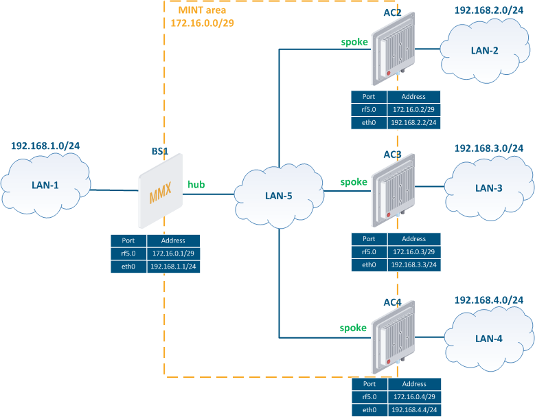
Figure 1 - The ODR protocol operation scheme in a star topology network
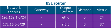

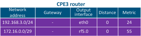

Table 1 - Wireless devices routing tables after pre-configuration
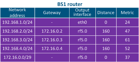
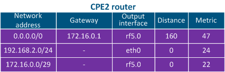
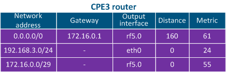
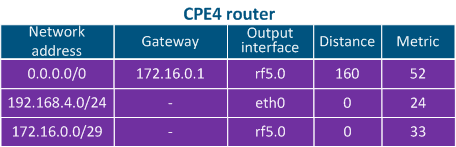
Table 2 - Wireless devices routing tables after ODR configuration
Usually ODR protocol is used in PTMP schemes (Figure 1), however, for a better understanding, let's complicate the scheme by implementing the balancing and fault tolerance function (Figure 2):
- two sectors BS1 and BS2, switches InfiMUX1 and InfiMUX2 are connected to Switch 1;
- two subscriber devices are connected to each sector: CPE11 and CPE12 to BS1, CPE21 and CPE22 to BS2;
- all devices are joined into a single MINT area (see InfiLINK 2x2 and InfiMAN 2x2: Switching);
- the InfiMUX1 and InfiMUX2 devices are configured as hubs, since they are connected to the external WAN, the wireless devices are configured as spokes.
Please note, a role is not a device characteristic, but a state of an interface that supports the MINT protocol operation. For example, a wireless device can be a hub in the MINT area, to which it is connected via the rf5.0 interface, and be a spoke in the MINT area, connected via the prf0 interface. In the example below, one common MINT area is used, therefore, for BS1 and BS2 devices, it is enough to activate the ODR protocol support on one of the interfaces that support MINT.
After preliminary configuration and roles distribution, CPE11, CPE12, CPE21 and CPE22 devices will add a default route to the routing table, specifying InfiMUX1 or InfiMUX2 as the gateway. The gateway will be selected by the lowest metric value to this device. Each hub device will receive routing information about user networks LAN-11, LAN-12, LAN-21, and LAN-22 from devices with spoke roles. Devices BS1 and BS2 are intermediate in this scheme and do not transmit routing information to devices with the hub role.
Fault tolerance: let's say that whole traffic passing through BS1 also passes through InfiMUX1, and BS2 traffic - through InfiMUX2. If InfiMUX1 fails, BS1, CPE11 and CPE12 devices will delete the entry with the InfiMUX1 gateway from the routing table, and add another default route via InfiMUX2 instead. A similar situation will occur in case of InfiMUX 2 failure.
Balancing: the default route metric in the ODR is calculated based on radio parameters and the channel load level. This allows balancing traffic for spoke devices and evenly utilizing devices and communication channels in the MINT area.
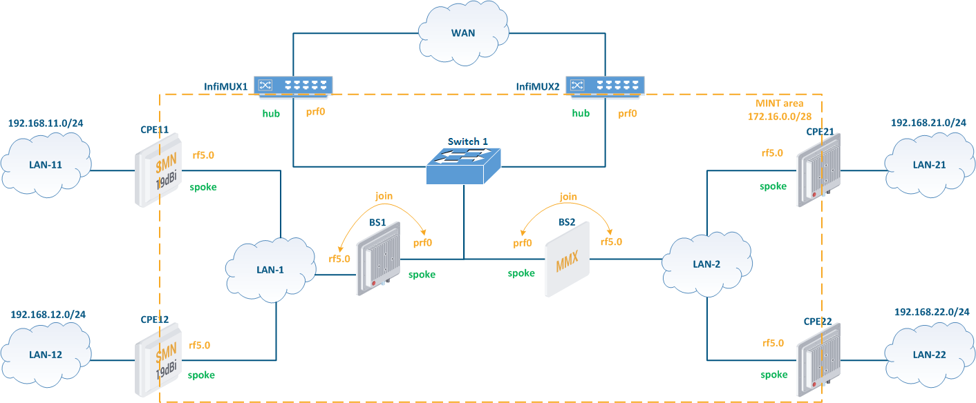
Figure 2 - Redundancy scheme using ODR protocol
ODR protocol features
Unlike the static routing, ODR protocol has following features:
- easy configuration: basic ODR configuration consists of roles distribution;
- scalability: an increase in the devices number on the network does not require a larger amount of work, it is enough to perform preliminary configuration on devices and define a role;
- rapidity: the state of devices and communication channels is constantly monitored by the ODR protocol, so changes in the network topology will instantly be reflected in the routing table;
- fault tolerance and traffic balancing: schemes implementation for increasing reliability and optimal links utilization does not require additional manipulations and is performed automatically;
- topology limitation: ODR cannot be used in arbitrary topology networks and is intended for star type networks;
- proprietary implementation: ODR protocol is supported by other hardware manufacturers, however these implementations will not be compatible with Infinet devices. This because the transport technology for ODR is not standardized and in Infinet devices the proprietary MINT protocol is used.
ODR practice
The examples of ODR configuration are on the document child page: ODR protocol configuration.