Successfully pass the free certification exam at IW Academy and become an Infinet Certified Engineer.
Checking radio settings
Pre-configuration in the lab
Before installing the devices to the sites, we recommend to configure the basic parameters in the lab and making sure that the link is establishing. Step-by-step instructions for a wireless link configuration are given in the "Setting up a basic PtP link" article, we also recommend to pass the "InfiLINK 2x2 / InfiMAN 2x2: Initial Link Configuration and Installation" online course.
NOTE
During devices configuration in a lab, take into account the following requirements:
- Make sure the devices are not directed at each other in order to prevent radio modules damage. It is possible to place devices at a distance from each other with antennas directed to the floor.
- A minimum transmit output power must be set on the devices.
- In case of two R5000-Omx or R5000-Lmn devices, it is recommended to connect them in the link directly, with RF cables and RF attenuators with attenuation of at least 40 dB for each polarization (installation\deinstallation of the RF attenuators and RF cables should only be performed when the devices are switched off).
- Failure or damage of the device radio module in case of these requirements violation void a warranty.
Checking radio parameters
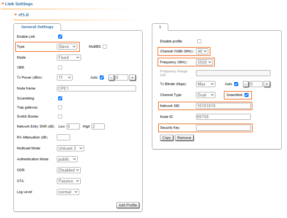
If the wireless link is not establishing in lab conditions: make sure the radio parameters are set to the values determined at the planning stage, the correct devices configuration can be obtained using the Configuration Generator on the IW Academy website. To establish a wireless link, one device must be configured as the Master, the second (all subscribers of the base station in the point-to-multipoint topology) - as the Slave. The following parameters must be identical on both devices:
- Channel Width.
- Frequency ("auto" settings are possible).
- Greenfield mode.
- Network SID.
- Security Key.
Web interface
To check the wireless link parameters go to the "Basic settings" - Link settings" section. Make sure the "Enable Link" checkbox is on.
Command line interface
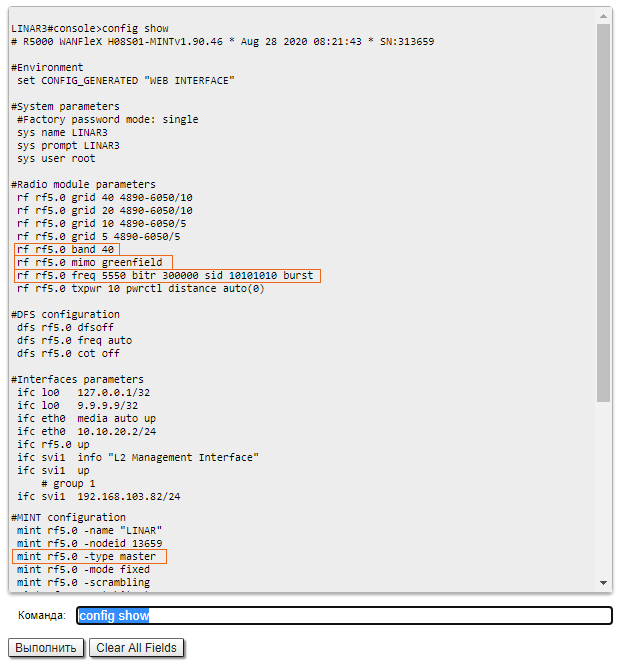
Use the "config show" command to check the configuration via the CLI.
Checking the radio interface status
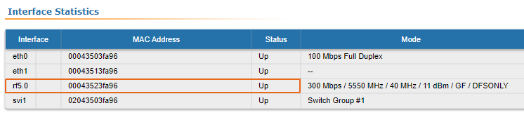
Make sure the radio interfaces of both devices are in the "Up" state.
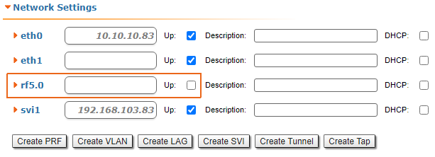
If the interface status is "Down", enable the radio interface in the "Network settings" section by clicking the checkbox.
If the device does not have a radio interface, the reason of such behavior can be the recovery mode during resetting the device using ERConsole. Complete the recovery process by returning the device to factory settings in the Maintenance section.
Checking the firmware version
Web interface
In the "Maintenance" section, make sure the same software version is installed on both devices: MINT or TDMA. Instructions for transmission between MINT and TDMA software versions are available in the article "How to upgrade your network from MINT to TDMA". We recommend to update devices to the latest beta software version.

The latest software versions can be downloaded from the official Infinet FTP server.
Command line interface
To upload software via the command line, use the "flashnet" command described in the "General Purpose Command Set" article.
Checking device placement requirements
Checking the network infrastructure
If the link is not established after installation on site, ensure that the devices were not damaged during shipping, check the integrity of the network infrastructure, cables and power supplies.
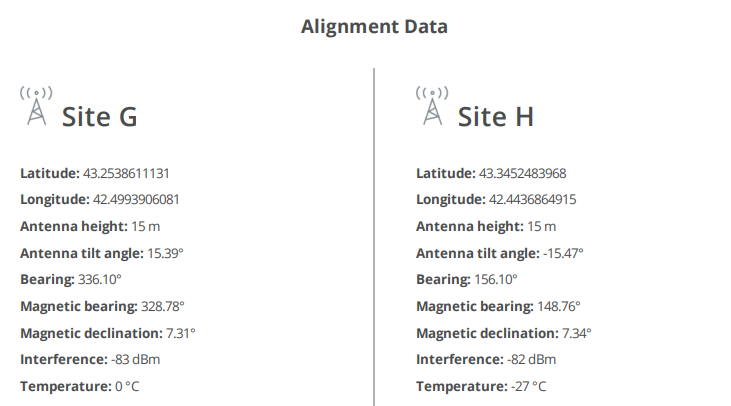
Checking placement requirements
Check if the suspension height, azimuth and elevation of the antenna match the values obtained from the InfiPLANNER. Убедитесь, что препятствия, находящиеся на профиле трассы, не выше указанных на этапе планирования.
Interference detection
Web interface
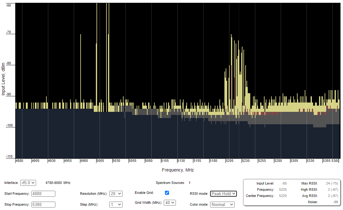
Using the built-in Spectrum Analyzer tool, scan the air on both sides of the link to make sure there is no interference that could corrupt the signal on the devices operating frequency and on adjacent frequencies. The current modulation (bit rate) will be selected by the device depending on the carrier to interference and noise ratio (CINR). To operate at higher modulations, the CINR parameter must be greater or equal to 28 dB. To get accurate information about the frequency hover the mouse cursor over it. The pop-up window below provides information about frequency, noise level (in dBm), maximum signal level (Max RSSI), average signal level (Average RSSI). The "High RSSI" indicator allows to estimate the number of signal sources, if the value differs significantly from the average RSSI, then there are several interference sources. The indicators show the signal level in dB, the signal in dBm is indicated in parentheses.
NOTE
It is recommended to run spectrum scanning simultaneously on both devices to avoid misrepresentation due to the signal received from the remote device.
Command line interface
The radio environment analysis is also available via the command line using the "muffer sensor" command.