| Include Page | ||||
|---|---|---|---|---|
|
Table of contents
| Table of Contents | ||
|---|---|---|
|
...
- Information - knowledge about the world and the processes in it, perceived by a person or a special device.
- Information Security (IS) - the security of the information and of the infrastructure components against influences that may harm the subjects of information relationswhich helps to ensure information confidentiality and integrity.
- Technical company policy - a set of technical solutions necessary to be used by the company's technical systems. The technical policy includes requirements for installation, operation and configuration of the devices. It is necessary to carry out periodical updates of the document and check its proper implementation.
- Threat - potential violation of the information security.
- Attack - attempt to realize a threat. An attack can be either malicious or not.
- Attacker - a person or group of people making an attack.
- Echelon - a subject for attack prevention, implemented as a part of an information security policy.
- Risk - the likelihood of a specific threat.
- Responsibility area - a network segment which has a certain subject responsible for its effective operation. A subject can be either a specific person or an organization.
- Internal network segment - a network segment that is in the responsibility area of our organization.
- External network segment - a network segment that is under the responsibility of a third-party organization or client. Since the external network segment is managed by a third-party organization, the crossing of the internal and the external network segments is a source of threats.
...
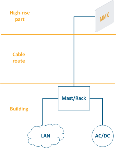
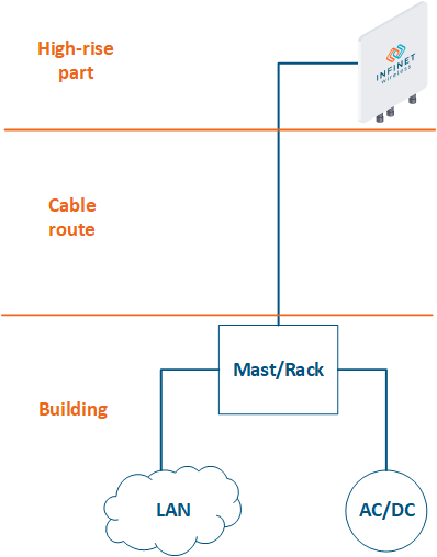
- High-rise part: the location of wireless devices, for example, the roof of a building, a mast, a telecommunication tower.
- Cable route: cables connecting the high-rise part and the equipment located indoor.
- Building: equipment located indoor and points of connection to the infrastructure. The infrastructure may include data channels, power, climate systems, etc. The equipment should be placed in a rack or in a telecommunication enclosure, which can be placed in a dedicated room or can be combined with the high-rise part of the object.
| Center |
|---|
Figure 2 - Communication node block diagram |
...
Equipment installation
The installation work on the site should be guided by the general requirements and by the company's technical policy. Improperly executed, the installation can cause a violation of the entire network facility availability, the restoration of which may require a large time and financial resources.
In order to ensure the physical security, make perform the following settings for the wireless device:
- turn off the indicator lights on the device, it will increase its stealth;
- the unused ports of the wireless devices can be used by an attacker to gain access to the network, therefore, in order to eliminate the possibility of unauthorized connections, it is recommended to disable the unused network interfaces;
- the devices based on the H11 hardware platform support the PoE-out function on eth1. An attacker can use it to power third-party equipment. If the PoE-out function is not used, make sure it is disabled.
Facility operation
The installation quality control of the installation is carried out at in the stage phase of the acceptance into service of the device. The acceptance procedure should be performed in accordance with the company's technical policy.
Ensuring the information security is a continuous process that requires monitoring and response to identified and emerging threats, therefore, it is necessary to carry out preventive maintenance of for the communication facilities. Depending on the requirements established by the company and the specifics of the network node, the list of preventive measures may vary. A common set of regular jobs includes:
...
| Tip | ||||||||||||||||||||||||||||||||||||||||||||||||||||||||||||||||||||||||||
|---|---|---|---|---|---|---|---|---|---|---|---|---|---|---|---|---|---|---|---|---|---|---|---|---|---|---|---|---|---|---|---|---|---|---|---|---|---|---|---|---|---|---|---|---|---|---|---|---|---|---|---|---|---|---|---|---|---|---|---|---|---|---|---|---|---|---|---|---|---|---|---|---|---|---|
| ||||||||||||||||||||||||||||||||||||||||||||||||||||||||||||||||||||||||||
| ||||||||||||||||||||||||||||||||||||||||||||||||||||||||||||||||||||||||||
| Anchor | ||||
|---|---|---|---|---|
|
Wireless data transmission is performed in a shared environment, which brings a lot of possibilities for the attackers. The security measures described below should be applied in a comprehensive manner, since measures protecting from one threat may not be effective against another.
...
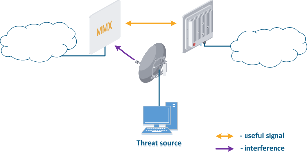
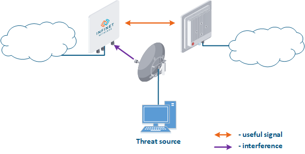
The frequency resource is limited, so the frequencies distributing process frequency distribution between wireless systems should be taken comprehensivelycarefully considered. Third-party wireless systems operating at on the same or on adjacent frequencies can affect the link (Figure 3). Usually, such an influence is not malicious, but it should be considered as a threat, since it leads can lead to the link operation failure. Our task is to search and select a frequency channel free of interference. Keep in mind that interference may not be present at the installation stage, but may appear during the wireless system operation.
Following The following actions can reduce the risks associated with this threat:
- Search for interference sources: devices devices of the InfiLINK 2x2 and , InfiMAN 2x2, InfiLINK Evolution, InfiMAN Evolution families allow you to obtain the MAC addresses of the systems operating in the selected frequency channel using the Radio scanner utility , it make or "muffer" command. It is possible to identify the source of interference and to decide on the measures to eliminate its effect on the link.
- Manual spectrum scan: manual preliminary radio survey of the territory in which the communication system will be deployed. The frequency is selected taking into account the scan scanned data. Infinet devices allow to evaluate the state of the spectrum using the built-in "Spectrum analyzer" utilitytool.
- Auto spectrum scan: radio survey of the territory in which the communication system is deployed, performed periodically in automatic mode. The frequency channel can be automatically changed in accordance with the scan scanned data. Infinet devices support the DFS and iDFS technology technologies (see Dynamic Frequency Selection), which are designed to automatically scan the spectrum.
| Center |
|---|
Figure 3 - An example of a threat in the frequency channel |
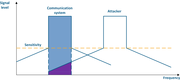
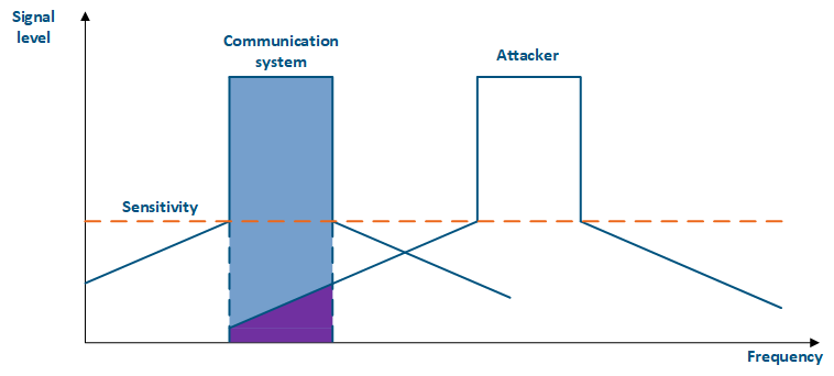
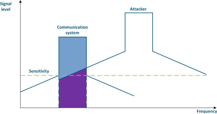
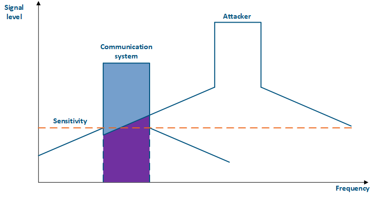
Even if a the frequency channels distribution is coordinated, the problem of mutual interference may persist. That happens due to an out-of-band radiation: a radiation spectrum is not an ideal rectangle. It has side bands that affect adjacent frequency channels. Below are the spectra of two communication systems (Figure 4 a-b) which using adjacent frequency channels: in the first case (Figure 4a), the radiation power of the systems is equal and the threat attacking source's influence is lower than the communication system's sensitivity, in the second case (Figure 4b), the radiation power of the threat attacking source is higher than the one of the communication system and the out-of-band level is higher than sensitivity, it will affect the communication system's sensitivity, leading to interference in the interference formcommunication.
The automatic transmit power control (ATPC) function can help to reduce the influence of a third-party communication system on the used frequency channels. In case of interference, the devices with having ATPC active ATPC will increase the radiation power and keep maintain the link performance.
The link budget depends also on the used modulation-coding scheme: higher MCS MCSs require higher link parameters, therefore, they are impossible to use with a low signal level and a high level of interference. Thus, the modulation-code scheme selection is a compromise between the link performance and reliability. The automatic modulation control (AMC) function allows to select a the selection of the modulation-coding scheme in accordance with according to the current parameters of the radio and change it in accordance with the situationlink. This allows to increase increases the reliability and the availability of the information, by keeping the link operability operational even in strong interference conditions.
For more information about signals signal's frequency characteristics, proceed to the online course "Wireless Networking Fundamentals".
| Center |
|---|
Figure 4a - An example of an adjacent frequency channel influence on a communication system
Figure 4b - An example of an adjacent frequency channel influence on a communication system |
Authentication Settings
Popular scenarios of for the information confidentiality and integrity violation in a radio channel are the attacks of the Man-In-The-Middle type (MITM). Let's look at the examples of such attackattacks:
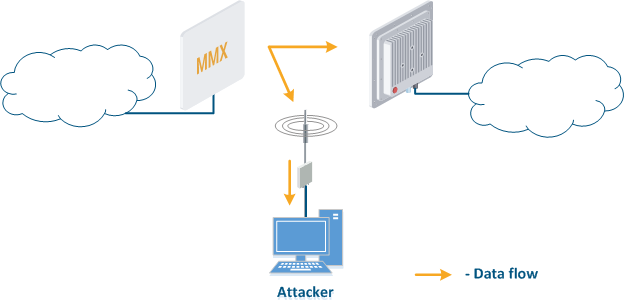
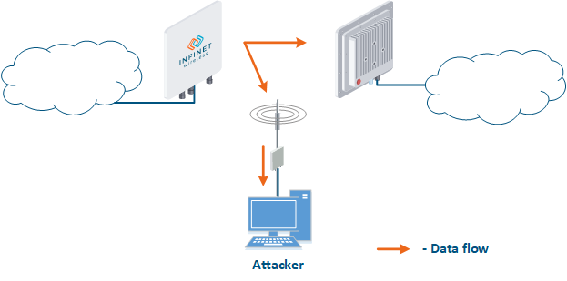
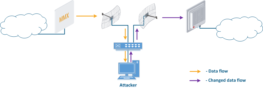
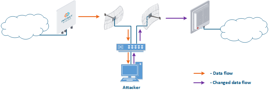
- Data interception (Figure 5a): the attacker installs a device that receives all the transmitted signals in the communication system's coverage area. All wireless systems use a shared data transmission medium, so the devices receive data even if they are not specified as a recipients. Further, the device processes the frame at the L2 layer , 2 if it is its the recipient, or discards it, if it is not. An attacker can pretend to be the recipient and gain an access to all messages, along with a legal addresseeaddress.
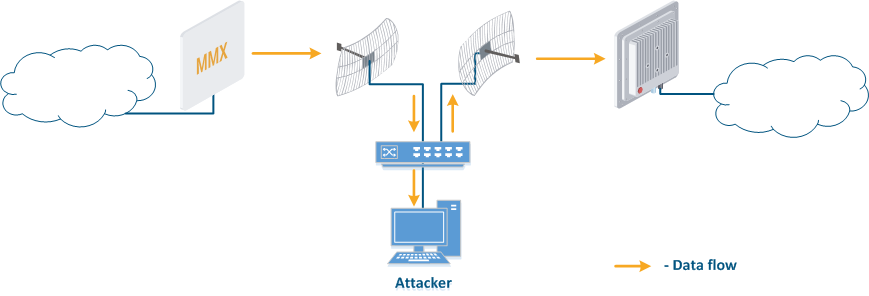
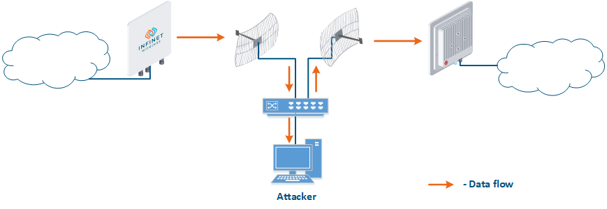
- Data relay (Figure. 5b): a specific case of of the "Data interception" scenario, in which an attacker uses a relay instead of a passive receiver. Such an attack option is applicable for example for point-to-point links with a narrow radiation pattern, where the Data Interception scenario is not suitable.
- Data spoofing (Figure 5c): a specific case of the "Data relay" scenario, in which the attacker changes the data during relaycontent. In such a scenario, not only confidentiality is violated but data integrity as well.
| Center |
|---|
Figure 5a - Data interception
Figure 5b - Data relay
Figure 5c - Data spoofing |
Also scenarios of obtaining There are also possible scenarios in which unauthorized access to the resources can be obtained through a connection to a radio network are possible. Let's look at the examples of such attackattacks:
- Connection to an enterprise network (Figure 6): an attacker with a subscriber device can install it in the base station coverage area. After establishing a link with the base station sector, an attacker can gain access to the enterprise network and implement attacks aimed at integrity, availability and confidentiality violation. An attacker will be able to establish a link with a base station sector only if the an Infinet wireless device is used.
| Center |
|---|
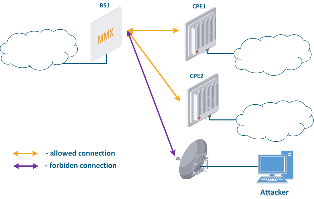 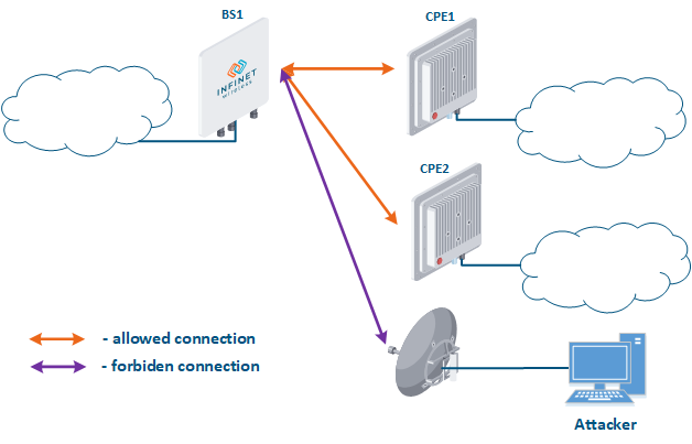 Figure 6 - Connection to an enterprise network |
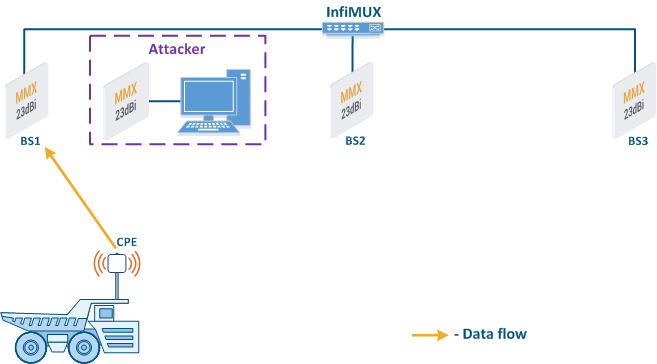
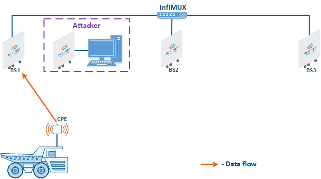
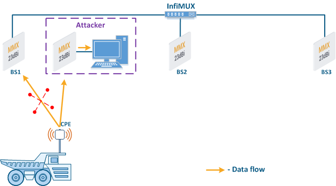
- Base station sector substitution (Figure 7a-b): an attacker installs a base station sector to which a subscriber station can connect. After that the attacker gains unauthorized access to the data originating from the subscriber station and to the network segment behind the subscriber station. Let's look at the example examples of such an attack in scenarios with the using mobile objects (see Connectivity with mobile objects). The A radio link is established between BS1 and the CPE (Figure 7a), the . The CPE is inttalled installed on the mobile object and breaks the connection while moving away from BS1 and starts to look for a new base station sector to set establish a connection (Figure 7b). An attacker set inserts a base station sector along the CPE's route, between BS1 and BS2, therefore, after disconnecting from BS1, the CPE establishes a connection with the attacker's sector. This attack type implementation is only possible only in case of disregarding the security settings disregarding.
| Center |
|---|
Figure 7a - Connection of the CPE station to the enterprise base station sector
Figure 7b - Connection of the CPE station to the attacker's base station sector |

The Infinet devices use their own radio frame format, making it makes impossible to organize a establish communication between with any devices operating according to the 802.11 family standards and Infinet devices. This This complicates the attacker's plans, as he will be forced to use Infinet devices.
...
- Link ID: always change the default value to unique.
- Security key: devices can establish a connection only if they have the same link ID and security key, i.e. in order to reduce the likelihood of organizing establishing a link with an attacker's device, security keys must be installed on both devices.
- Authentication Mode: The InfiLINK 2x2 and , InfiMAN 2x2, InfiLINK Evolution, InfiMAN Evolution family devices support authentication mode settings when establishing a wireless link. "Static" and "remote" modes can limit the list of devices with which the link installation establishment is allowed. The The static mode allows to set configure a list of devices MAC addresses of the devices with which a connection can be established (white list), or a list of addresses with which the connection establishment is forbidden (black list). The The remote method allows to store MAC addresses for whitelists or blacklists centrally and perform appropriate requests when trying to establish a connection. Using one of the described authorization methods will significantly complicate an unauthorized connection of an attacker to the network.
- Max links: sets the maximum allowed number of connected CPEs. It is recommended to set the value of the actual subscriber stations number.
- Scrambling: reversible process of redistributing the data bits in accordance with according to a given algorithm in order to equalize the frequency spectrum of the signal. Scrambling also make makes it difficult to decrypt the intercepted data, because the attacker must have know the descrambling scrambling algorithm that was used in order to recover the original bit sequence. ScramblingThe scrambling/descrambling operations will require hardware resources, therefore it is recommended to use this option in cases of low hardware load.
- Frequency grid: the frequencies frequency range supported by the radio module can be deliberately limited using the frequency grid on all Infinet devices. This restriction narrows down the list of frequencies that can be set as central. The frequency grid additional effect is to increase the level of the device protection from against choosing a random frequency channel as a operational. If the automatic center frequency selection is set, then the device will select it in accordance with according to the grid. The center frequency can be set manually: on Master devices, the center frequency is set strictly, on Slave devices, depending on the family, either strictly or using one or more radio profiles. If a subscriber station uses several radio profiles (see Connectivity with mobile objects), then while connecting in order to connect to the base station sector, the profiles will be sorted scanned until finding a successful connectionparameter match.
- Global function: in scenarios with mobile objects, the Global option is used to connect a subscriber station to base stations sectors that are connected to the network core (see Connectivity with mobile objects). This approach can be used to block the CPE connections to base stations sectors installed by attackers (Figure 7b): since the attacker's base station is not connected to the network core, the subscriber station will ignore the attacker device during roaming.
| Anchor | ||||
|---|---|---|---|---|
|
Unauthorized The unauthorized access to the device's management interface is a serious threat that can lead to a violation of all the basic data properties, measures . Measures to ensure the information security and to reduce the potential risks should be elaborated carefully.
...
| Warning | ||
|---|---|---|
| ||
By default, one user is added to the configuration with administrative rights and with the following login values:
Since the default authentication settings allows a high probability of unauthorized access, change the username and password during initial setup. |
A company can have several lines of technical support: in such a scheme, some problems that do not require wireless devices device reconfiguration can be solved by the first line of technical support. Thus, trivial tasks can be solved without qualified employees of the second and third lines of technical support. To implement this scenario, a guest account can be added to the device's configuration. A user which has access to the management interface using a guest account can use the utilities tools and view interface statistics, but he it is not allowed to make configuration changes.
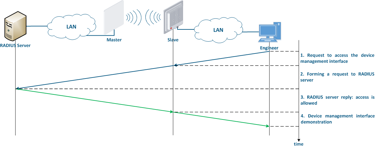
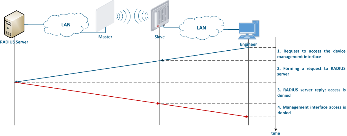
It is recommended to use a centralized account storage for networks with having a large number of devices. This allows to avoid errors when blocking accounts, provide provides a single password policy and have a single interface for accounts account management. Infinet devices support the RADIUS protocol, which is intended for centralized authentication, authorization and account management in networks. Depending on the capabilities and on the scale of the network, the database for the RADIUS operation can be deployed on a separate device, or combined with other network elements.
| Expand | ||
|---|---|---|
| ||
The algorithm for a RADIUS server usage is the following (Figure 8):
|
...
Infinet devices can be configured using the Web GUI or the command line interface (CLI). Some parameters can only be configured via CLI. Access to different interfaces is carried out using various network protocols. It is recommended to disable the unused protocols, in order to reduce the possibility probability of unauthorized access to the device's management interface.
The management protocols supported by the Infinet devices correspond to the management interfaces in a the following way:
- Web GUI:
- HTTP: data are is transmitted over the network unencrypted, so an attacker, gaining access to the network, can intercept themit.
- HTTPS: data are is transmitted over the network encrypted, so an attacker who intercepts the data will not be able to decrypt it without the corresponding encryption keys. Unless there are specific reasons for using HTTP, the HTTPS protocol should be used.
- CLI:
- Telnet: data are is transmitted over the network unencrypted, so an attacker, gaining access to the network, can intercept themit. Telnet The telnet protocol is acceptable in case of emergency, when there is no possibility of using SSH.
- SSH: data are is transmitted over the network encrypted. In case that an attacker intercepts the data, he will not be able to decrypt it without the corresponding encryption keys.
...
The network management interface (mgmt), which is used to access the device is organized differently in different structured differently, depending on the device families:
- InfiLINK XG, InfiLINK XG 1000, Quanta 5, Quanta 6 and Quanta 570: for device management is allocated an internal virtual interface is allocated, which can be associated with an IP address.
- InfiLINK 2x2, InfiMAN 2x2, InfiLINK Evolution and InfiMAN 2x2Evolution: an IP address can be associated with virtual or physical interfaces, i.e. various interfaces can act as a network management interface, for example eth0, svi100. Several network management interfaces of the same or of different types can be added to the configuration.
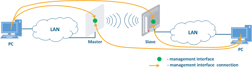
In addition to selecting the the management interface, it is also possible to control the connectivity between the management interface and the other network interfaces. This mechanism allows to restrict the access to the device via wired or wireless interfaces, depending on the scenario.
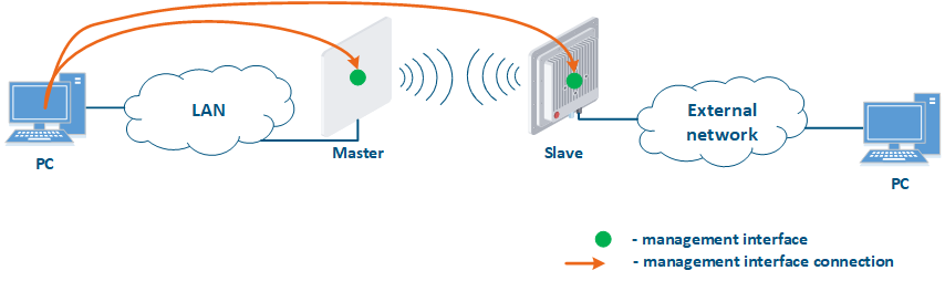
Figure 1 demonstrates the scenarios for shows some practical scenarios when using Infinet devices usage. Let's look at the device management configuration for each scenario. To do In this sense, we have added the PCs connected to different network segments in order to perform the devices management configuration (Figure 9a-c):
- Joining of internal network segments: access to the devices' management interfaces should be provided to PC users from different network segments (Figure 9a). Wireless The wireless devices are located on the internal network and do not directly contact the external network devices. The function of protecting against unauthorized access should be performed by the network elements located at the border of between the internal and the external networks.
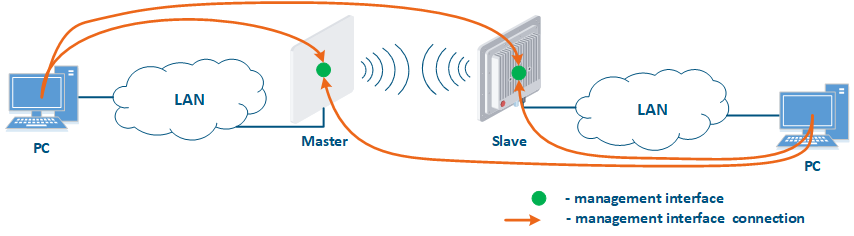
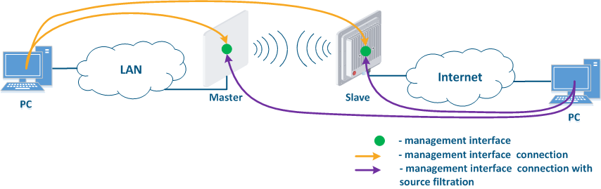
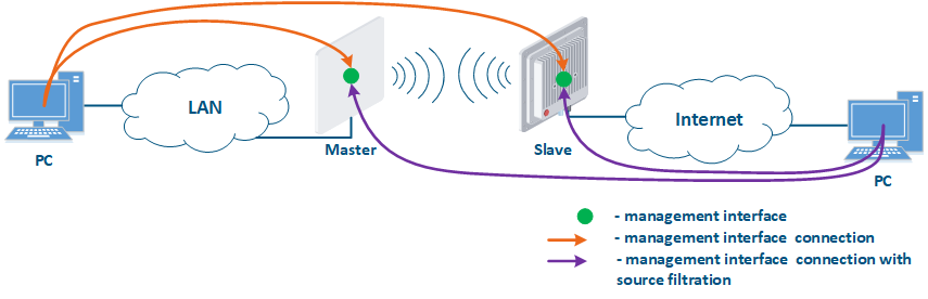
- Connection of the internal and the external network segments: access to the device's management interface should be granted only to a PC user connected to the local network segment (Figure 9b), i.e. the ability to transfer data between the management interface and the Slave's device wired interface should be disabled.
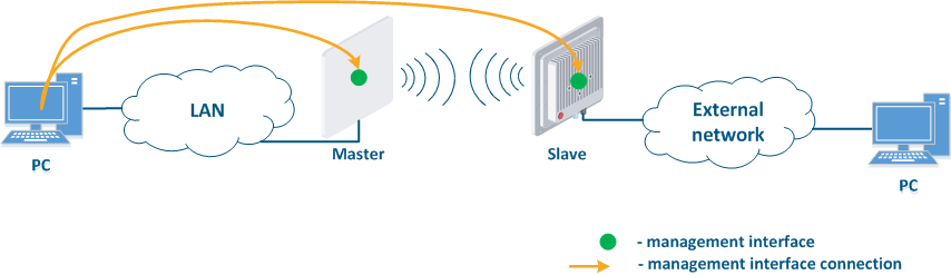
- Internal Connection of the internal network segment connection with the Internet: access to the device's management interface should be granted only to a PC user connected to the local network segment (Figure 9c). In addition, access may be granted to some PC users connected to the Internet. In this case, incoming traffic filtering must be configured on border devices, as it is shown below.
| Center |
|---|
Figure 9a - Radio link joining internal network segments
Figure 9b - Radio link connecting internal and external network segments
Figure 9c - Radio link connecting an internal network segment with the Internet |
We recommend to use the following principles of management configuration:
- Use the virtual interface as management interface:
- InfiLINK XG, InfiLINK XG 1000, Quanta 5, Quanta 6 and Quanta 5 70 family devices: network management interface (mgmt).
- InfiLINK 2x2 and , InfiMAN 2x2 family devices: network interface svi connnected with switch group for management traffic, InfiLINK Evolution and InfiMAN Evolution family devices: svi network interface attached to the management switch group.
- Access to the management interface should be allowed only through the network interfaces , connected to the engineers' PC or through the services that manage devices, for example, a monitoring system.
- In the case of network traffic isolation using a VLAN, a separate VLAN must be allocated for the management traffic and associated with the management interface.
| Anchor | ||||
|---|---|---|---|---|
|
InfiLINK IInfiLINK 2x2, InfiMAN 2x2, InfiLINK Evolution, Quanta 5, Quanta 6 and Quanta 5 70 family devices allows allow to create white access lists. In this case, only the network nodes which whose IP addresses are mentioned in the list will be permitted to access the management interface.
| Anchor | ||||
|---|---|---|---|---|
|
The ERConsole utility is used to restore an the access to all Infinet devices (see the "ERConsole" screencast). The utility tool can be used for the following purposes:
- Error in the device's configuration: ERConsole utility the ERConsole tool allows to assign an IP address to the interface, or reset the device to factory settings in case of a fatal errors in configuration.
- Device protection against an attacker: To reset the Infinet device to the factory settings, a factory password is required, which is assigned to the company that purchased it. If the device is stolen by an attacker, he will not be able to get the factory password from the technical support, cause because he is not an employee of the enterprise, which means he will not be able to access the device.
| Tip | ||||||||||||||||||||||||||||||||||||||||||||||||||||||||||||||||||||||||||||||||||||||||||
|---|---|---|---|---|---|---|---|---|---|---|---|---|---|---|---|---|---|---|---|---|---|---|---|---|---|---|---|---|---|---|---|---|---|---|---|---|---|---|---|---|---|---|---|---|---|---|---|---|---|---|---|---|---|---|---|---|---|---|---|---|---|---|---|---|---|---|---|---|---|---|---|---|---|---|---|---|---|---|---|---|---|---|---|---|---|---|---|---|---|---|
| ||||||||||||||||||||||||||||||||||||||||||||||||||||||||||||||||||||||||||||||||||||||||||
| ||||||||||||||||||||||||||||||||||||||||||||||||||||||||||||||||||||||||||||||||||||||||||
| Anchor | ||||
|---|---|---|---|---|
|
Data transmission is the main function of any network equipment. In addition to user data, the devices exchange service messages of auxiliary protocols such as SNMP, LLDP, etc. The described functions implementation different's protocols design contains potential threats that an attacker can use , and requires accurate configuration of all the wireless devices device subsystems.
| Anchor | ||||
|---|---|---|---|---|
|
Wireless systems are hardware and software systems. Therefore, one of the most important requirements is the timely software updating. It is recommended to use stable software versions and monitor the release of updates. Used The current software version can be checked directly on the device.
When making changes to the devices device's configuration, keep in mind that the mechanism for applying the settings depends on the used management interface used:
- Web GUI: changes made in different sections of the interface are accumulated and sequentially added to the configuration only after clicking the "Apply" button. When the device is rebooted, the last successfully saved configuration will be loaded.
- CLI: the command is instantly added to the current configuration, but not saved. To save the settings, run the appropriate command. When the device is rebooted, the last successfully saved configuration will be loaded.
In some cases, errors made during the device's configuration process can lead to losing access loss to the device and and the device may need to be reset to factory settings (see "Access recovery"). To reduce the risk of this scenario, it is recommended to use a delayed device reboot. In this case, after applying the new configuration, a device availability check will be performed. If the device is unavailable, the previous version of the configuration will be restored.
...
By default, switching on the device is configured to pass data between the wired and wireless interfaces without filtrationany filtering. Such a scheme is vulnerable to a large amount of spurious traffic, which can take up all the available throughput and the link will actually become inaccessible for the transmission of useful traffic. An example of spurious traffic is a broadcast storm, which can cause errors in devices switching. Measures The measures to protect the network infrastructure from such attacks are:
- Traffic filtering: a good practice is to split the physical infrastructure into multiple virtual local area networks using the VLAN technology. This method allows to limit broadcast domains, and thus reduce the impact of a broadcast storm. This will require traffic filtering of different VLANs on devices: for wireless devices it is recommended to permit allow only those VLAN tags that really should be transmitted through the radio link and deny all the others.
- STP: Spanning Tree Protocol is designed to prevent link-level loops that could cause a broadcast storm. In addition, the STP protocol can be used to build automatic backup schemes at the L2 layer in networks with redundancy.
- Router mode: Routing technology can reduce the size of the broadcast segment that will lead to the a lower impact of the broadcast storm. A router is a device that divides broadcast domains, i.e. a broadcast storm in one domain will not affect the operation of the devices in another domain. Routing also involves the packets packet transmission based on the IP header with a TTL field included, which prevents packets from cycling through the network.
...
In addition to user data, the devices exchange service messages of auxiliary protocols. The security policy should take into account that any available service is a potential attacker's target.
...
Infinet devices can be configured as a DHCP client, DHCP server and or DHCP relay. Keep in mind that the DHCP protocol supports not only the IP address allocation, but also the network settings transmission.
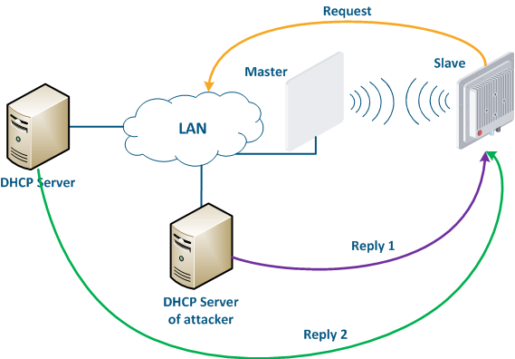
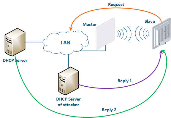
Let's look at the example of the an attack using the DHCP (Figure 10): there a link is link established between the Master and Slave, a DHCP client is activated on the Slave's device radio interface and the DHCP server is installed on the corporate network. In this example the attacker managed to connect to the network device on which the DHCP server is configured to within the corporate network. After the Master-Slave link has been established, the Slave device sends a broadcast request to the network to receive the network settings from the DHCP server. DHCP The DHCP servers located on the network respond to a the request from Slave. If the response from the attacker server is received first, the Slave device will assign to the network interface the proposed address and network settings that are transmitted in this request. Thus, an attacker can set his device as the default router and gain access to the traffic transmitted by the Slave device.
| Center |
|---|
Figure 10 - An example of the attack using the DHCP |
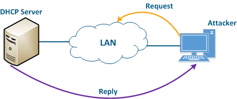
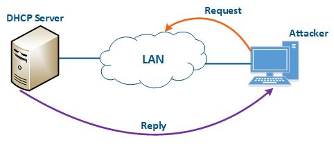
An attacker’s device can also act as a DHCP client (Figure 11): the functions of network DHCP server are is implemented on the Infinet device, while an attacker’s device is connected to the network. In a situation where the DHCP server configuration protocol does not provide security measures, the attacker will generate a request and the server will provide the device with the network details. Thus, an attacker will gain access to data transmitted over the network.
| Center |
|---|
Figure 11 - An example of the attack using the DHCP |
In order to increase the security of when using DHCP in the a corporate network, it is recommended to implement the following measures:
- DHCP servers list limitation by DHCP at the DHCP client: The DHCP client allows to limit the list of servers for which a network settings request will be generated. In this case, the DHCP client will generate requests for the specified DHCP servers, if they do not respond, it will generate a broadcast request.
- Security key usage: a security key can be used during the client authentication. Keep in mind that this setting must be performed both on the DHCP server and on the DHCP client.
- Client-address pair in a DHCP server configuration: the DHCP server configuration allows to record the IP addresses allocated to clients. Thus, it is possible to create white lists of devices, so the obtaining that obtaining the network details will become complicated for an attacker.
- DHCP Snooping: this technology allows to prevent receiving network details from the attacker's DHCP server. The operation principle is very simple: the Ethernet ports, behind which the DHCP server is located, are marked as trusted, the rest as untrusted. Messages from DHCP servers that arrived at the untrusted ports will be discarded, which makes it impossible for client devices to obtain network details from the attacker's server.
- Disable DHCP on unused interfaces: the list of interfaces on which DHCP is enabled should be carefully monitored. Disable DHCP on interfaces that are not used for data transfer or use static addressing. This recommendation is actual for both the DHCP client and the DHCP server.
- Refuse of DHCPStatic configuration: keep in mind that the DHCP usage must be limited, a lot of scenarios require the a static assignment of the network details settings to the corresponding interfaces. For example, it is recommended to assign static addresses to key network elements, which may include Infinet wireless devices. This will help to avoid problems in organizing technical accounting and monitoring systems.
ARP
The Ethernet and the IP protocols belong to different levels layers of the network interaction model, .In order to bind the addresses of the devices used in each of the protocols by each protocol, a special tool protocol is needed. ARP protocol and the with its address mapping table that it fills are used for this purpose. The table contains entries where the MAC address of the interface is mapped to the IP address , that is used when transmitting IP packets encapsulated in Ethernet frames.
Let's look at the an example of an attack with using IP address spoofing: two clients (Client 1 and Client 2) have an access to the Internet via the Master-Slave radio link. An The IP address assigned to the client is an identifier for the appointment of with a tariff plan. The client with the IP address 192.168.0.1 is provided with a throughput of 10 Mbit/s, the client with the address 192.168.0.2 - with 2 Mbit/s (Figure 12a). At some point Client 1 turns off the PC and does not use the provider services, at the same time Client 2 replaces its IP address with the 192.168.0.1 address assigned to Client 1 (Figure 12b). In this case Client 2 will gain access to the Internet with greater throughput, and Client 1 after switching on, will have problems with access to in accessing the network.
| Center |
|---|
Figure 12a - An example of the attack using IP spoofing
Figure 12b - An example of the attack using IP spoofing |
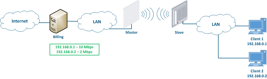
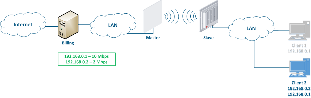
This type of attacks with IP address spoofing attack can be prevented by adding a static record to the ARP protocol address mapping table. In this case, Client's 2 data will not be transmitted after changing the IP address, because the address 192.168.0.1 will be is assigned to the MAC address of Client 1.
...
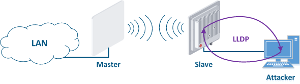
The LLDP protocol is designed to exchange service information about a device with its directly connected devices. The service information is can be the VLAN ID, the MAC address, the device's name, the IP address of the management interface, etc. If an attacker will gain physical access to the device, then by launching the LLDP service on his PC, he will be able to get service obtain information about the device by exchanging service messages (Figure 13). This information can help the attacker to get unauthorized access to the device.
To prevent this type of attack, follow the these guidelines:
- Global LLDP disabling: if the technical policy of the company does not require the LLDP usage, it is recommended to disable its operation on all network devices.
- LLDP disabling on interfaces: if it is necessary to use LLDP, then it should be allowed only on those network interfaces to which network infrastructure elements are connected.
| Center |
|---|
|
SNMP
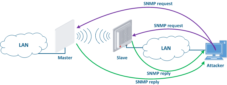
SNMP was created as a unified protocol for managing network devices and collecting data on about their state. The protocol provides for two types of requests: a request to GET some parameter value and a request to SET the specified parameter specified value. Thus, the devices that support SNMP can operate in read mode (only GET requests) and write mode (SET and GET requests). SNMP The SNMP server activation is necessary for centralized device management by using a monitoring system. But an attacker could take his chance if the SNMP server is not configured properly. In this case, he can not only get information about the network structure, but also change the configuration of the device (Figure 14).
To prevent unauthorized access follow the these guidelines:
- SNMPv3: by default, SNMPv1 and SNMPv2c support is activated on the devices , - a community with the name "public" is created. The SNMPv1 and SNMPv2c protocols provide authentication using the community name, which is openly transmitted over the network. SNMPv3 is recommended to use be used due to the implementation of authentication and of message encryption.
- Read only mode: if the SNMP SET mode is not used, then its support must be disabled. This will reduce the potential consequences of unauthorized access.
- White lists: Infinet devices allow to create white lists of access to the SNMP server.
| Center |
|---|
Figure 14 - An example of the attack using SNMP |
MINT
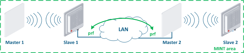
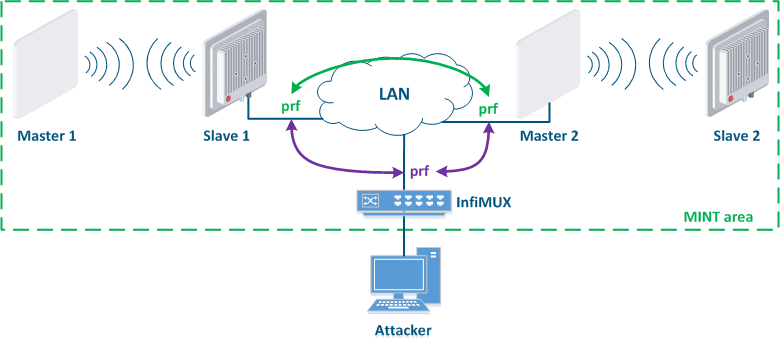
MINT is the proprietary Infinet protocol, whose operation can be organized in the wired and in the wireless segments. An attacker, gaining access to the MINT domain, can compromise all network devices related connected to this domain, therefore, pay special attention while configure when configuring the MINT protocol.
Let's look at the example of an attack using the MINT protocol: two wireless links Master 1 - Slave 1 and Master 2 - Slave 2 are joined into the a MINT area using PRF interfaces (Figure 15a). The attacker get gets physical access to the enterprise network using the InfiMUX switch, on which the a PRF interface is created (Figure 15b). PRF interfaces will establish communication channels between each other and all devices will be combined joined into a MINT area, so an attacker will receive information about the devices in this area and will be able to execute remote commands on them using MINT tools.
Protection against such attacks:
- Security key: the PRF interface is a virtual radio interface operating in a wired environment, therefore, same as for wireless interfaceinterfaces, the PRF interface supports the ability to install configure a security key. In this case, the link between two PRF interfaces will be organized established only if their security keys match.
- Password for remote commands execution: one of the MINT protocol tools is the ability to remotely execute commands on a device located in the same MINT area. By default, remote command execution is available without a password, set the . Set a password to limit the capabilities rights of the attacker.
| Center |
|---|
Figure 15a - Joining links in the MINT area
Figure 15b - An example of the attack using the MINT protocol |
| Tip | ||||||||||||||||||||||||||||||||||||||||||||||||||||||||||||||||||||||||||||||||||||||||||||||||||||||||||||||||||||||||||||||||||||||
|---|---|---|---|---|---|---|---|---|---|---|---|---|---|---|---|---|---|---|---|---|---|---|---|---|---|---|---|---|---|---|---|---|---|---|---|---|---|---|---|---|---|---|---|---|---|---|---|---|---|---|---|---|---|---|---|---|---|---|---|---|---|---|---|---|---|---|---|---|---|---|---|---|---|---|---|---|---|---|---|---|---|---|---|---|---|---|---|---|---|---|---|---|---|---|---|---|---|---|---|---|---|---|---|---|---|---|---|---|---|---|---|---|---|---|---|---|---|---|---|---|---|---|---|---|---|---|---|---|---|---|---|---|---|---|
| ||||||||||||||||||||||||||||||||||||||||||||||||||||||||||||||||||||||||||||||||||||||||||||||||||||||||||||||||||||||||||||||||||||||
| ||||||||||||||||||||||||||||||||||||||||||||||||||||||||||||||||||||||||||||||||||||||||||||||||||||||||||||||||||||||||||||||||||||||
Anchor infrastructure infrastructure
Infrastructure
| infrastructure | |
| infrastructure |
Infrastructure The infrastructure security is the important section of an important aspect concerning the information security, which needs a requires special attention. Infrastructure character The infrastructure implementation depends on the technical policy of the enterprise. The network should contain have functionalities such as logging, monitoring and technical record-keeping.
...
Monitoring systems can be integrated with alarm systems and video surveillance.
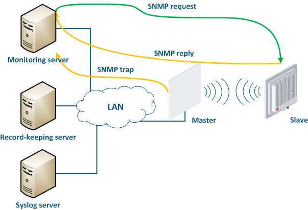
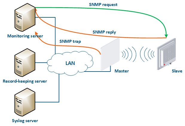
Infinet company provides its own system for monitoring the Infinet wireless devices - InfiMONITOR. The monitoring system collects data in the following ways (Figure 16):
- Polling: the monitoring system sends SNMP requests to the device devices, demanding the specific parameters whose values must be received. The device generates an SNMP response for the monitoring system, where it indicates the values of the requested parameters. Device parameters The device parameter polling is carried out with a set periodicity, which guarantees that each device will be requested interrogated in a given interval.
- Traps: the device sends a special SNMP Trap message to the monitoring server in case of an incident from the specified list. SNMP The SNMP Trap sending is initiated by the device itself and occurs instantly, regardless of the polling cycle, however, this will require additional device configuration.
| Center |
|---|
Figure 16 - Data exchange between devices and a monitoring system |
...
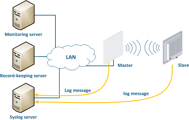
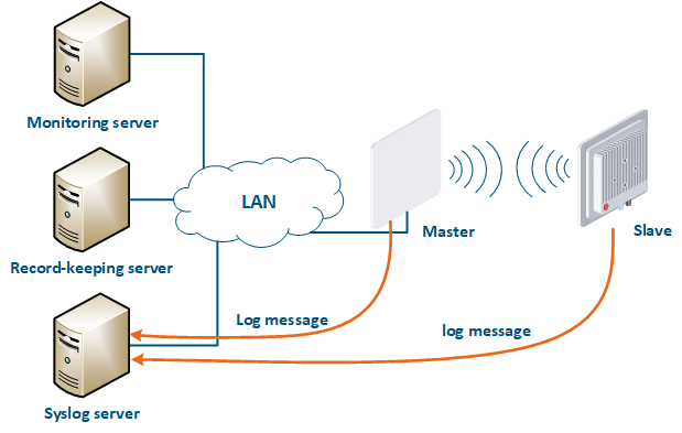
A detailed incident investigation requires an analysis of the system logs stored on the device. Infinet devices support logging, but the system log will be lost after a device reboot. In large networks it is useful to have a centralized repository of log files, such . Such a repository has an interface which allows to display all the network's devices logs used in necessary for the incident investigation.
A Syslog server is allocated on the network for these purposes. All log entries are sent to the Syslog server simultaneously with writing to the system log (Figure 17). This allows to centrally store the message history of all the network devices message history centrally , without the risk to lose of losing all syslog data in case of device reboot or unauthorized access.
| Center |
|---|
Figure 17 - Data exchange with the Syslog server |
...
Operational problems solving, to gain access to the facility, to restore the configuration , and add it to the monitoring system, etc requires a comprehensive information about the devices. Such information includes both technical and administrative aspects. Special technical record-keeping systems can be used on the network to store the data and have access to it. Technical record-keeping systems contain the following information:
- Device info: indicates the device model, its serial number and network details.
- Site info: indicates the device location, information about access to the site, contact information, etc.
- Text device configuration: The the device configurations 's configuration history can be used for the during incident investigation and for device operation restorerestoring, therefore, configurations configuration backups should be performed regularly. Some technical record-keeping systems can be joined with systems of mass devices configuration on the network: such systems allow to unifiy devices configurations, unify the configuration of the devices and the network is assumed seen as a single device for which the history of changes is stored.
| Tip | |||||||||||||||||||||||||||||||||||||||||||||||||||||||||||||||||||||||||||||||||||
|---|---|---|---|---|---|---|---|---|---|---|---|---|---|---|---|---|---|---|---|---|---|---|---|---|---|---|---|---|---|---|---|---|---|---|---|---|---|---|---|---|---|---|---|---|---|---|---|---|---|---|---|---|---|---|---|---|---|---|---|---|---|---|---|---|---|---|---|---|---|---|---|---|---|---|---|---|---|---|---|---|---|---|---|
| |||||||||||||||||||||||||||||||||||||||||||||||||||||||||||||||||||||||||||||||||||
| |||||||||||||||||||||||||||||||||||||||||||||||||||||||||||||||||||||||||||||||||||
Additional materials
Online courses
- InfiLINK 2x2 / InfiMAN 2x2: Initial Link Configuration and Installation.
- InfiLINK XG Family Product.
- Quanta 5 / Quanta 6: Installation and Configuration.
- Wireless Networking Fundamentals.
- InfiLINK 2x2 and InfiMAN 2x2: Switching.
...