| Include Page | ||||
|---|---|---|---|---|
|
Table of contents
| Table of Contents | ||
|---|---|---|
|
...
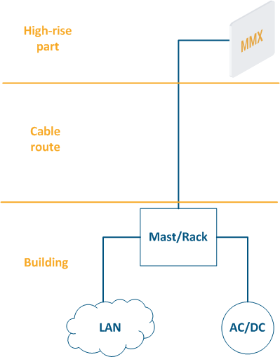
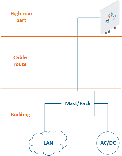
- High-rise part: the location of wireless devices, for example, the roof of a building, a mast, a telecommunication tower.
- Cable route: cables connecting the high-rise part and the equipment located indoor.
- Building: equipment located indoor and points of connection to the infrastructure. The infrastructure may include data channels, power, climate systems, etc. The equipment should be placed in a rack or in a telecommunication enclosure, which can be placed in a dedicated room or can be combined with the high-rise part of the object.
| Center |
|---|
Figure 2 - Communication node block diagram |
...
| Tip | ||||||||||||||||||||||||||||||||||||||||||||||||||||||||||||||||||||||||||
|---|---|---|---|---|---|---|---|---|---|---|---|---|---|---|---|---|---|---|---|---|---|---|---|---|---|---|---|---|---|---|---|---|---|---|---|---|---|---|---|---|---|---|---|---|---|---|---|---|---|---|---|---|---|---|---|---|---|---|---|---|---|---|---|---|---|---|---|---|---|---|---|---|---|---|
| ||||||||||||||||||||||||||||||||||||||||||||||||||||||||||||||||||||||||||
| ||||||||||||||||||||||||||||||||||||||||||||||||||||||||||||||||||||||||||
| Anchor | ||||
|---|---|---|---|---|
|
...
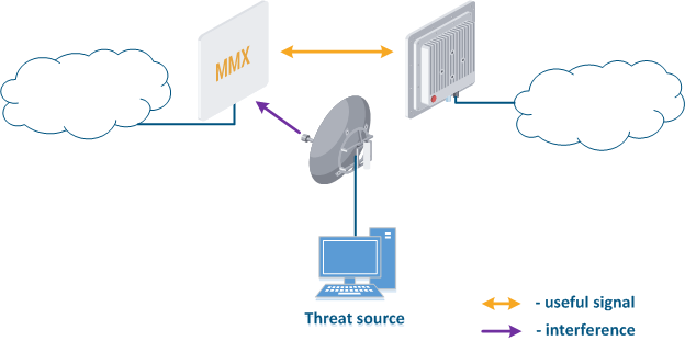
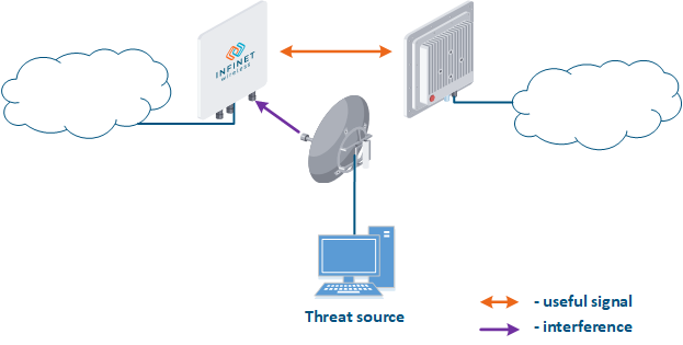
- Search for interference sources: devices devices of the InfiLINK 2x2 and , InfiMAN 2x2, InfiLINK Evolution, InfiMAN Evolution families allow you to obtain the MAC addresses of the systems operating in the selected frequency channel using the Radio scanner utility or "muffer" command. It is possible to identify the source of interference and to decide the measures to eliminate its effect on the link.
- Manual spectrum scan: manual preliminary radio survey of the territory in which the communication system will be deployed. The frequency is selected taking into account the scanned data. Infinet devices allow to evaluate the state of the spectrum using the built-in "Spectrum analyzer" tool.
- Auto spectrum scan: radio survey of the territory in which the communication system is deployed, performed periodically in automatic mode. The frequency channel can be automatically changed in accordance with the scanned data. Infinet devices support the DFS and iDFS technologies (see Dynamic Frequency Selection), which are designed to automatically scan the spectrum.
| Center |
|---|
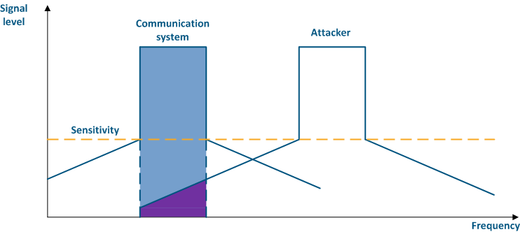
Figure 3 - An example of a threat in the frequency channel |
...
For more information about signal's frequency characteristics, proceed to the online course "Wireless Networking Fundamentals".
| Center |
|---|
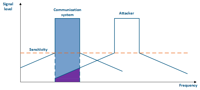
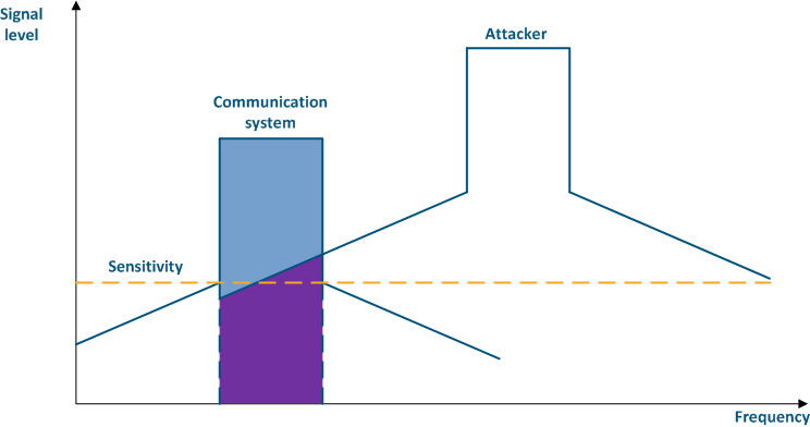
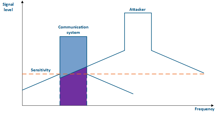
Figure 4a - An example of an adjacent frequency channel influence on a communication system
Figure 4b - An example of an adjacent frequency channel influence on a communication system |
...
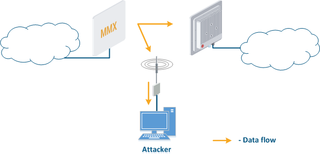
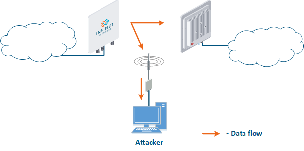
- Data interception (Figure 5a): the attacker installs a device that receives all the transmitted signals in the communication system's coverage area. All wireless systems use a shared data transmission medium, so the devices receive data even if they are not specified as recipients. Further, the device processes the frame at layer 2 if it is the recipient, or discards it, if it is not. An attacker can pretend to be the recipient and gain access to all messages, along with a legal address.
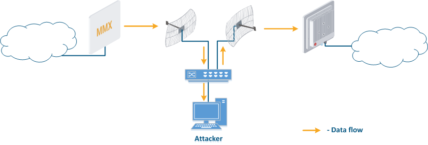
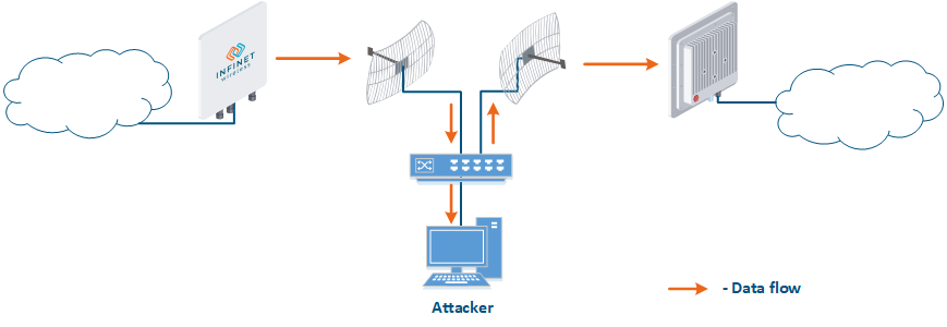
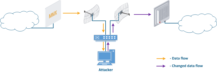
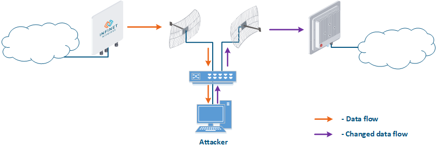
- Data relay (Figure. 5b): a specific case of the "Data interception" scenario, in which an attacker uses a relay instead of a passive receiver. Such an attack option is applicable for example for point-to-point links with a narrow radiation pattern, where the Data Interception scenario is not suitable.
- Data spoofing (Figure 5c): a specific case of the "Data relay" scenario, in which the attacker changes the data content. In such a scenario, not only confidentiality is violated but data integrity as well.
| Center |
|---|
Figure 5a - Data interception
Figure 5b - Data relay
Figure 5c - Data spoofing |
...
- Connection to an enterprise network (Figure 6): an attacker with a subscriber device can install it in the base station coverage area. After establishing a link with the base station sector, an attacker can gain access to the enterprise network and implement attacks aimed at integrity, availability and confidentiality violation. An attacker will be able to establish a link with a base station sector only if an Infinet wireless device is used.
| Center |
|---|
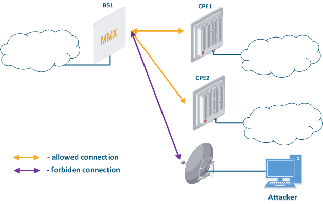 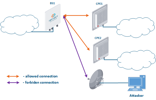 Figure 6 - Connection to an enterprise network |
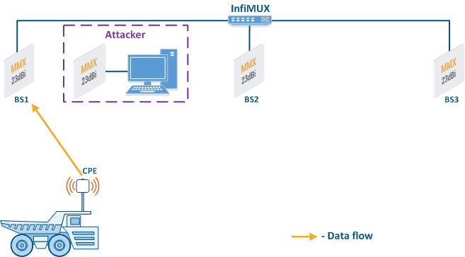
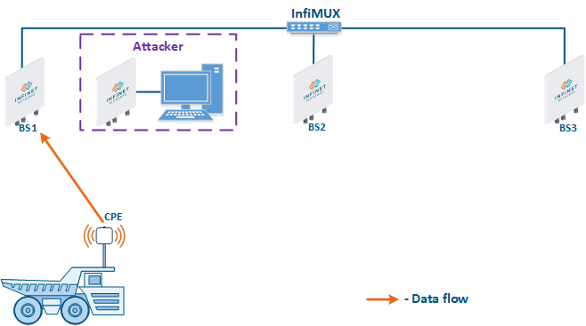
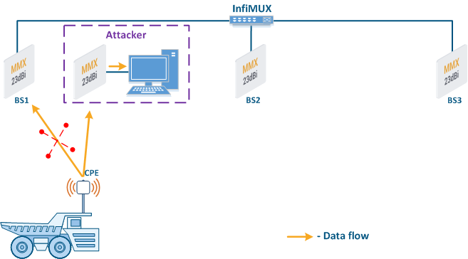
- Base station sector substitution (Figure 7a-b): an attacker installs a base station sector to which a subscriber station can connect. After that the attacker gains unauthorized access to the data originating from the subscriber station and to the network segment behind the subscriber station. Let's look at examples of such an attack in scenarios using mobile objects (see Connectivity with mobile objects). A radio link is established between BS1 and the CPE (Figure 7a). The CPE is installed on the mobile object and breaks the connection while moving away from BS1 and starts to look for a new base station sector to establish a connection (Figure 7b). An attacker inserts a base station sector along the CPE's route, between BS1 and BS2, therefore, after disconnecting from BS1, the CPE establishes a connection with the attacker's sector. This attack type implementation is only possible in case of disregarding the security settings.
| Center |
|---|
Figure 7a - Connection of the CPE to the enterprise base station sector
Figure 7b - Connection of the CPE to the attacker's base station sector |

...
- Link ID: always change the default value to unique.
- Security key: devices can establish a connection only if they have the same link ID and security key, i.e. in order to reduce the likelihood of establishing a link with an attacker's device, security keys must be installed on both devices.
- Authentication Mode: The InfiLINK 2x2 and , InfiMAN 2x2 family , InfiLINK Evolution, InfiMAN Evolution family devices support authentication mode settings when establishing a wireless link. "Static" and "remote" modes can limit the list of devices with which the link establishment is allowed. The The static mode allows to configure a list of MAC addresses of the devices with which a connection can be established (white list), or a list of addresses with which the connection establishment is forbidden (black list). The The remote method allows to store MAC addresses for whitelists or blacklists centrally and perform appropriate requests when trying to establish a connection. Using one of the described authorization methods will significantly complicate an unauthorized connection of an attacker to the network.
- Max links: sets the maximum allowed number of connected CPEs. It is recommended to set the value of the actual subscriber stations number.
- Scrambling: reversible process of redistributing the data bits according to a given algorithm in order to equalize the frequency spectrum of the signal. Scrambling also makes it difficult to decrypt the intercepted data, because the attacker must know the scrambling algorithm that was used in order to recover the original bit sequence. The scrambling/descrambling operations will require hardware resources, therefore it is recommended to use this option in cases of low hardware load.
- Frequency grid: the frequency range supported by the radio module can be deliberately limited using the frequency grid on all Infinet devices. This restriction narrows down the list of frequencies that can be set as central. The frequency grid additional effect is to increase the level of protection against choosing a random frequency channel as operational. If the automatic center frequency selection is set, then the device will select it according to the grid. The center frequency can be set manually: on Master devices, the center frequency is set strictly, on Slave devices, depending on the family, either strictly or using one or more radio profiles. If a subscriber station uses several radio profiles (see Connectivity with mobile objects), then in order to connect to the base station sector, the profiles will be scanned until finding a parameter match.
- Global function: in scenarios with mobile objects, the Global option is used to connect a subscriber station to base stations sectors that are connected to the network core (see Connectivity with mobile objects). This approach can be used to block the CPE connections to base stations sectors installed by attackers (Figure 7b): since the attacker's base station is not connected to the network core, the subscriber station will ignore the attacker device during roaming.
| Anchor | ||||
|---|---|---|---|---|
|
...
- InfiLINK XG, InfiLINK XG 1000, Quanta 5, Quanta 6 and Quanta 570: for device management an internal virtual interface is allocated, which can be associated with an IP address.
- InfiLINK 2x2, InfiMAN 2x2, InfiLINK Evolution and InfiMAN 2x2Evolution: an IP address can be associated with virtual or physical interfaces, i.e. various interfaces can act as a network management interface, for example eth0, svi100. Several network management interfaces of the same or of different types can be added to the configuration.
...
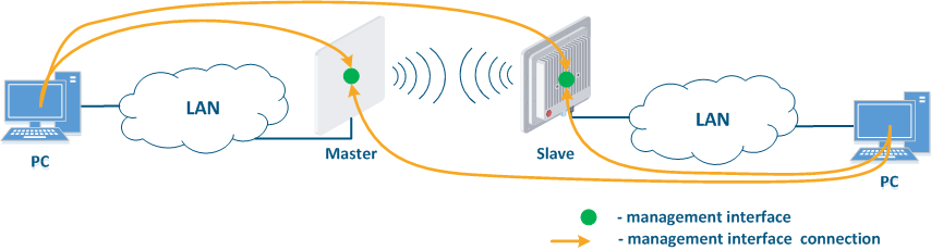
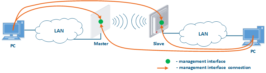
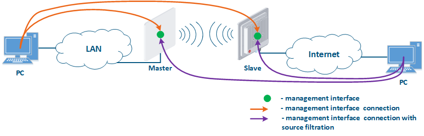
- Joining of internal network segments: access to the devices' management interfaces should be provided to PC users from different network segments (Figure 9a). The wireless devices are located on the internal network and do not directly contact the external network devices. The function of protecting against unauthorized access should be performed by the network elements located at the border between the internal and the external networks.
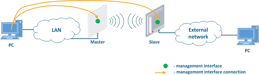
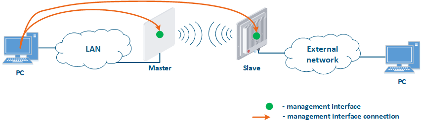
- Connection of the internal and the external network segments: access to the device's management interface should be granted only to a PC user connected to the local network segment (Figure 9b), i.e. the ability to transfer data between the management interface and the Slave's device wired interface should be disabled.
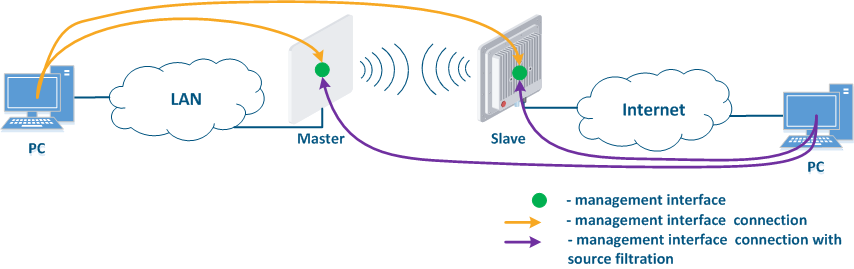
- Connection of the internal network segment with the Internet: access to the device's management interface should be granted only to a PC user connected to the local network segment (Figure 9c). In addition, access may be granted to some PC users connected to the Internet. In this case, incoming traffic filtering must be configured on border devices, as it is shown below.
| Center |
|---|
Figure 9a - Radio link joining internal network segments
Figure 9b - Radio link connecting internal and external network segments
Figure 9c - Radio link connecting an internal network segment with the Internet |
...
- Use the virtual interface as management interface:
- InfiLINK XG, InfiLINK XG 1000, Quanta 5, Quanta 6 and Quanta 5 70 family devices: network management interface (mgmt).
- InfiLINK 2x2, InfiMAN 2x2, InfiLINK Evolution and InfiMAN 2x2 Evolution family devices: svi network interface attached to the management switch group.
- Access to the management interface should be allowed only through the network interfaces connected to the engineers' PC or through the services that manage devices, for example, a monitoring system.
- In the case of network traffic isolation using a VLAN, a separate VLAN must be allocated for the management traffic and associated with the management interface.
| Anchor | ||||
|---|---|---|---|---|
|
InfiLINK IInfiLINK 2x2, InfiMAN 2x2, InfiLINK Evolution, Quanta 5, Quanta 6 and Quanta 5 70 family devices allow to create white access lists. In this case, only the network nodes whose IP addresses are mentioned in the list will be permitted to access the management interface.
...
| Tip | |||||||||||||||||||||||||||||||||||||||||||||||||||||||||||||||||||||||||||||||||||||||||
|---|---|---|---|---|---|---|---|---|---|---|---|---|---|---|---|---|---|---|---|---|---|---|---|---|---|---|---|---|---|---|---|---|---|---|---|---|---|---|---|---|---|---|---|---|---|---|---|---|---|---|---|---|---|---|---|---|---|---|---|---|---|---|---|---|---|---|---|---|---|---|---|---|---|---|---|---|---|---|---|---|---|---|---|---|---|---|---|---|---|
| |||||||||||||||||||||||||||||||||||||||||||||||||||||||||||||||||||||||||||||||||||||||||
| |||||||||||||||||||||||||||||||||||||||||||||||||||||||||||||||||||||||||||||||||||||||||
| Anchor | ||||
|---|---|---|---|---|
|
...
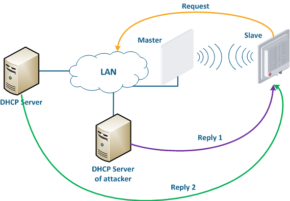
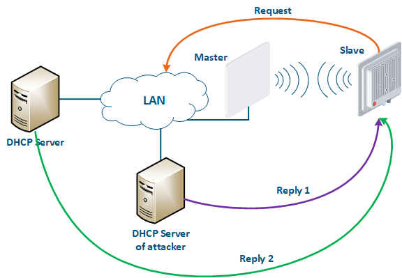
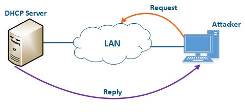
Let's look at the example of an attack using DHCP (Figure 10): a link is established between the Master and Slave, a DHCP client is activated on the Slave's device radio interface and the DHCP server is installed on the corporate network. In this example the attacker managed to connect to the network device on which the DHCP server is configured within the corporate network. After the Master-Slave link has been established, the Slave device sends a broadcast request to the network to receive the network settings from the DHCP server. The DHCP servers located on the network respond to the request from Slave. If the response from the attacker server is received first, the Slave device will assign to the network interface the proposed address and network settings that are transmitted in this request. Thus, an attacker can set his device as the default router and gain access to the traffic transmitted by the Slave device.
| Center |
|---|
Figure 10 - An example of attack using DHCP |
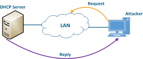
An attacker’s device can also act as a DHCP client (Figure 11): the DHCP server is implemented on the Infinet device, while an attacker’s device is connected to the network. In a situation where the DHCP server configuration protocol does not provide security measures, the attacker will generate a request and the server will provide the device with the network details. Thus, an attacker will gain access to data transmitted over the network.
| Center |
|---|
Figure 11 - An example of attack using DHCP |
...
| Tip | ||||||||||||||||||||||||||||||||||||||||||||||||||||||||||||||||||||||||||||||||||||||||||||||||||||||||||||||||||||||||||||||||||||||
|---|---|---|---|---|---|---|---|---|---|---|---|---|---|---|---|---|---|---|---|---|---|---|---|---|---|---|---|---|---|---|---|---|---|---|---|---|---|---|---|---|---|---|---|---|---|---|---|---|---|---|---|---|---|---|---|---|---|---|---|---|---|---|---|---|---|---|---|---|---|---|---|---|---|---|---|---|---|---|---|---|---|---|---|---|---|---|---|---|---|---|---|---|---|---|---|---|---|---|---|---|---|---|---|---|---|---|---|---|---|---|---|---|---|---|---|---|---|---|---|---|---|---|---|---|---|---|---|---|---|---|---|---|---|---|
| ||||||||||||||||||||||||||||||||||||||||||||||||||||||||||||||||||||||||||||||||||||||||||||||||||||||||||||||||||||||||||||||||||||||
| ||||||||||||||||||||||||||||||||||||||||||||||||||||||||||||||||||||||||||||||||||||||||||||||||||||||||||||||||||||||||||||||||||||||
Anchor infrastructure infrastructure
Infrastructure
| infrastructure | |
| infrastructure |
...
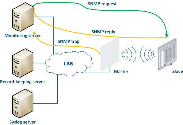
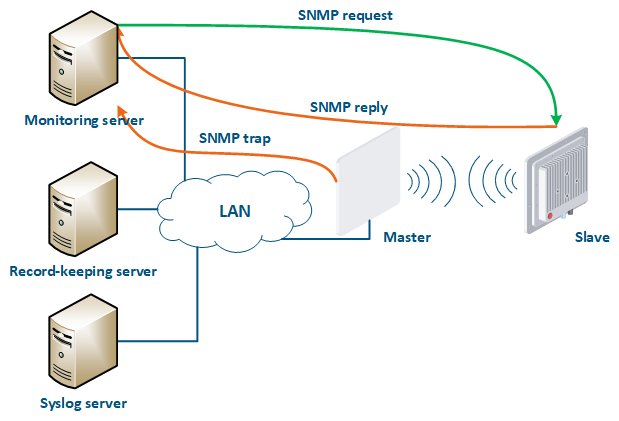
- Polling: the monitoring system sends SNMP requests to the devices, demanding specific parameters. The device generates an SNMP response for the monitoring system, where it indicates the values of the requested parameters. The device parameter polling is carried out with a set periodicity, which guarantees that each device will be interrogated in a given interval.
- Traps: the device sends a special SNMP Trap message to the monitoring server in case of an incident from the specified list. The SNMP Trap sending is initiated by the device itself and occurs instantly, regardless of the polling cycle, however, this will require additional device configuration.
| Center |
|---|
Figure 16 - Data exchange between devices and a monitoring system |
...
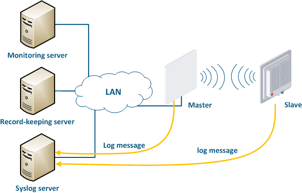
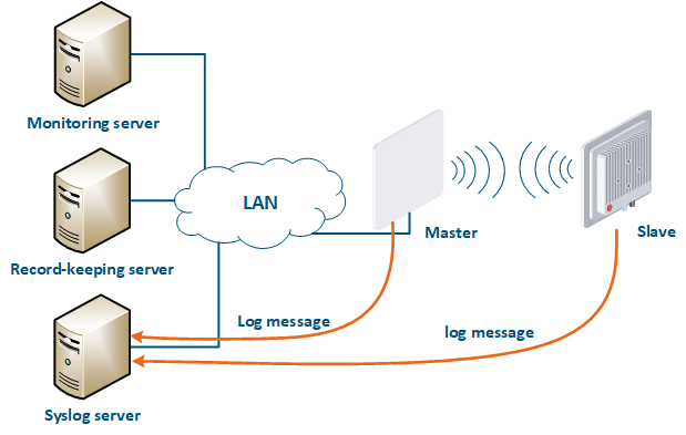
A Syslog server is allocated on the network for these purposes. All log entries are sent to the Syslog server simultaneously with writing to the system log (Figure 17). This allows to centrally store the message history of all the network devices, without the risk of losing all syslog data in case of device reboot or unauthorized access.
| Center |
|---|
Figure 17 - Data exchange with the Syslog server |
...
| Tip | |||||||||||||||||||||||||||||||||||||||||||||||||||||||||||||||||||||||||||||||||||
|---|---|---|---|---|---|---|---|---|---|---|---|---|---|---|---|---|---|---|---|---|---|---|---|---|---|---|---|---|---|---|---|---|---|---|---|---|---|---|---|---|---|---|---|---|---|---|---|---|---|---|---|---|---|---|---|---|---|---|---|---|---|---|---|---|---|---|---|---|---|---|---|---|---|---|---|---|---|---|---|---|---|---|---|
| |||||||||||||||||||||||||||||||||||||||||||||||||||||||||||||||||||||||||||||||||||
| |||||||||||||||||||||||||||||||||||||||||||||||||||||||||||||||||||||||||||||||||||
Additional materials
Online courses
- InfiLINK 2x2 / InfiMAN 2x2: Initial Link Configuration and Installation.
- InfiLINK XG Family Product.
- Quanta 5 / Quanta 6: Installation and Configuration.
- Wireless Networking Fundamentals.
- InfiLINK 2x2 and InfiMAN 2x2: Switching.
...